Near-air blind-area-free high-gain antenna and using method thereof

A high-gain antenna, no blind spot technology, applied in the direction of antenna support/installation device, etc., can solve the problems of antenna installation and site control, the three-dimensional size of the antenna is too large, the antenna efficiency and gain are low, and the difficulty of erection is low. , The effect of reducing the difficulty of erection and compressing the width

Pending Publication Date: 2021-05-28
河南爱科瑞特电子科技有限公司
View PDF5 Cites 1 Cited by
  • Summary
  • Abstract
  • Description
  • Claims
  • Application Information

AI Technical Summary

Problems solved by technology

like figure 1 As shown, the overall three-dimensional size of the antenna is too large, which brings a lot of trouble to the installation and site control of the antenna
[0005] In addition, in general, in order to achieve short-distance communication, communication stations often use short-distance antennas such as three-wire antennas and three-wire inverted V antennas to solve the problem of short-distance communication. However, due to the limitation of antenna radiation methods, the efficiency and gain of such antennas Both are low, and the log-periodic antenna with high gain is mostly used for long-distance communication, and radiates outward through low elevation angles. However, the log-periodic antenna with high gain is difficult to meet the high gain requirement at close range due to its strong directivity.

Method used


Image

  • Near-air blind-area-free high-gain antenna and using method thereof
  • Near-air blind-area-free high-gain antenna and using method thereof
  • Near-air blind-area-free high-gain antenna and using method thereof

Examples


Embodiment 1

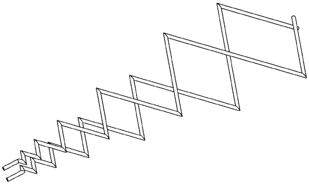
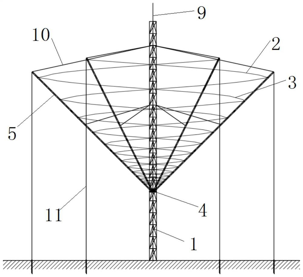
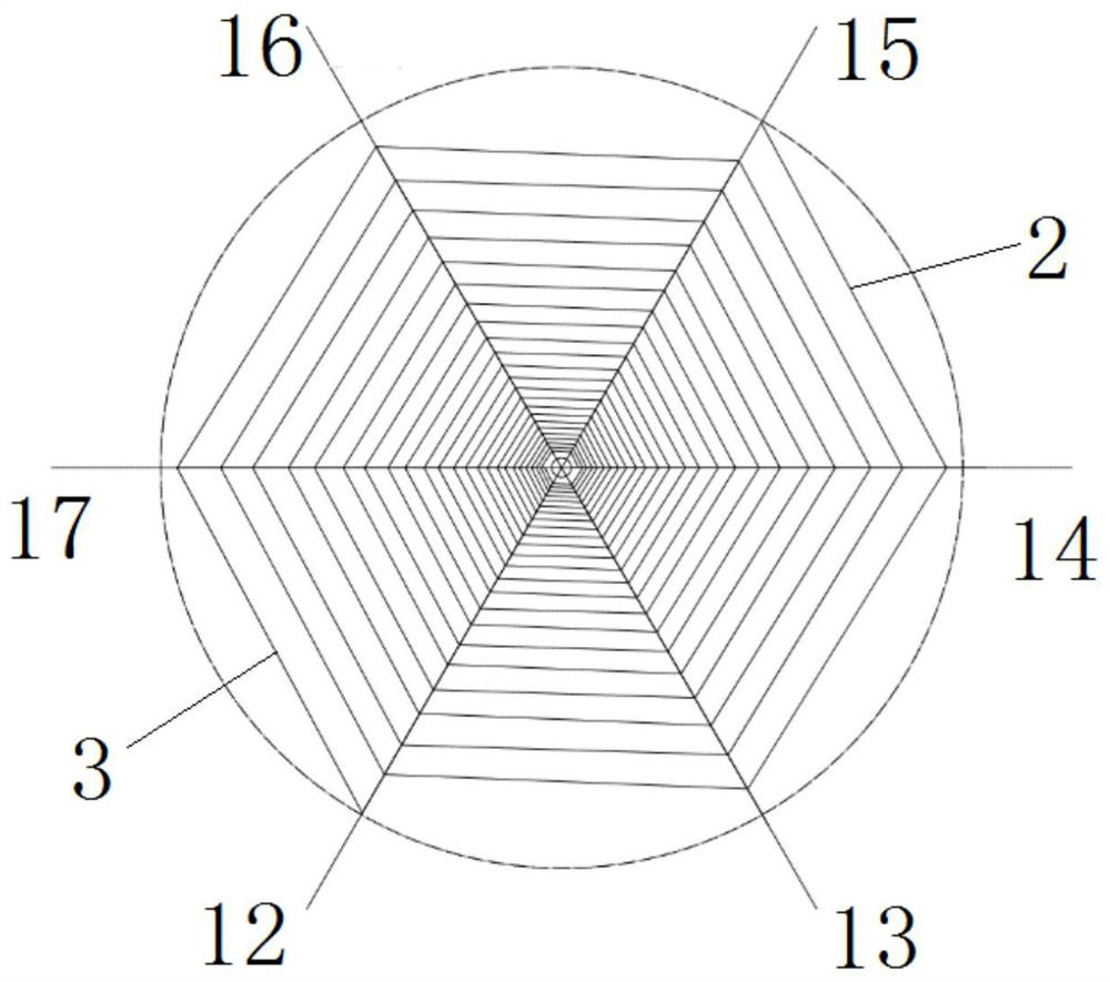
[0030] Such as figure 2 with 3 As shown, a near-air high-gain antenna without blind zone includes a central mast 1, a first antenna vibrator 2 and a second antenna vibrator 3, the central mast 1 is provided with an antenna base 4 concentric with the central axis 9, and the center of the antenna base 4 An antenna matcher 6 is provided at the position, and a plurality of obliquely upward support rods 5 are uniformly distributed along the circumferential direction on the antenna base 4. The plurality of support rods 5 are centered on the central axis 9 in a tapered layout. The support rods 5 and the central axis 9 The radial spacing gradually increases from bottom to top, the lower ends of the first antenna element 2 and the second antenna element 3 are respectively connected to the antenna matching device 6, and the upper ends of the first antenna element 2 and the second antenna element 3 are connected with the central axis 9 Symmetrical, and arranged spirally upward along th...

Embodiment 2

[0040] The near-air high-gain antenna without blind zone described in Embodiment 1 is used for short-distance communication, and the specific usage method is as follows: Image 6 As shown, the end of the antenna facing the ground 19 is the antenna transmitting end 18 (that is, the lower end of the first antenna element 2 and the second antenna element 3). After the antenna is powered on, the antenna transmitting end 18 transmits a beam to the ground 19, and then the beam passes through the ground 19 once It is reflected to the sky ionosphere 20, and then reflected to the ground 19 through the sky ionosphere 20 for the second time.

[0041] Due to the high gain of the logarithmic periodic antenna, the beam width emitted by the antenna is small, so the beam width reflected by the ground 19 is also small, and after being reflected back to the ground 19 by the ionosphere 20 in the sky, the communication coverage of the antenna satisfies short-distance omnidirectional requirements,...


PUM


Abstract

The invention provides a near-air blind-area-free high-gain antenna and a using method thereof. A log-periodic antenna comprises a central mast, a first antenna oscillator and a second antenna oscillator, the central mast is provided with an antenna base with the same central axis, the central position of the antenna base is provided with an antenna matcher, a plurality of obliquely upward supporting rods are evenly distributed on the antenna base in the circumferential direction, the radial distance between the supporting rods and the central mast is gradually increased from bottom to top, the lower ends of the first antenna oscillator and the second antenna oscillator are connected with the antenna matcher, and the upper ends of the first antenna oscillator and the second antenna oscillator are symmetrical about the central axis. And the inner sides of the plurality of supporting rods are spirally and upwards expanded in the same direction. The width of the antenna is reduced by increasing the circumferential size of the antenna, so that the width of the antenna is greatly compressed, the erection difficulty of the antenna is reduced, and the high-gain requirement of near field communication is met.

Description

technical field [0001] The invention relates to the technical field of logarithmic periodical antennas, in particular to a high-gain near-space antenna with no dead zone and a method for using the same. Background technique [0002] The logarithmic periodic antenna is a kind of non-frequency-variable antenna. It has good broadband characteristics and is widely used in broadband wireless transmission. In the short-wave band, the log-periodic antenna is currently the only one that can use a pair of antennas to work in the entire short-wave band and maintain good electrical performance of the broadband antenna. [0003] The logarithmic periodic dipole antenna is the basic form of the logarithmic periodic antenna. It is formed by cross-connecting N parallel dipoles with double wires. The parallel dipoles on are of varying lengths and spacing, but remain parallel to each other. Therefore, the logarithmic periodic dipole antenna can also be regarded as a coplanar linear array fo...

Claims


Application Information

Patent Timeline
Patent Type & Authority Applications(China)
IPC IPC(8): H01Q1/12
CPCH01Q1/12
Inventor 陈竞涛宋永政沈小琪杨海兵汪战豪
Owner 河南爱科瑞特电子科技有限公司
Why Eureka
Try Eureka