Heater control device
A control device and heater technology, which is applied to electric heating devices, circuit devices, heating element materials, etc., can solve problems such as power-on time limitation and heat limitation released by electric heaters.
- Summary
- Abstract
- Description
- Claims
- Application Information
AI Technical Summary
Problems solved by technology
Method used
Image

Examples
no. 1 approach
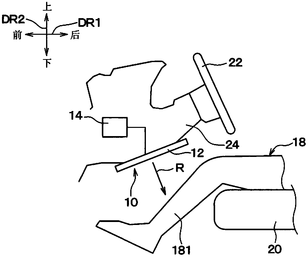
[0033] Such as figure 1 As shown, in this embodiment, the heater system 10 is a component mounted on a vehicle, and the heater system 10 includes an electric heater 12, a heater control device 14, and a heater operating unit 26 (see Figure 5 ). here, figure 1 Arrows DR1 and DR2 in the arrows indicate the direction of the vehicle on which the heater system 10 is mounted. which is, figure 1 An arrow DR1 in the arrow indicates a vehicle front-rear direction DR1, and an arrow DR2 indicates a vehicle up-down direction DR2.
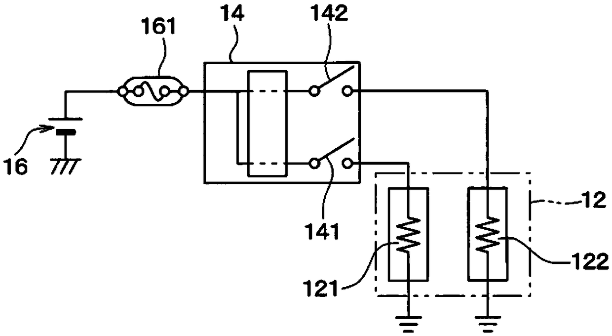
[0034] The electric heater 12 is a thin-plate-shaped radiation heater, and is arranged in the vehicle interior. Such as figure 1 as well as figure 2 As shown, the electric heater 12 is powered by a power source 16 such as a battery mounted on a vehicle or a generator, and generates heat. Specifically, the electric heater 12 has a plurality of heat generating parts 121 and 122 that generate heat by energization, and radiates heat from the plurality of h...
no. 2 approach
[0088] Next, a second embodiment will be described. In this embodiment, differences from the first embodiment described above will be mainly described. In addition, description of the same or equivalent parts as those of the above-mentioned embodiment is omitted or simplified. This point also applies to the embodiments described later.
[0089] In this embodiment, if Figure 9 As shown, the heater control device 14 controls the electric heater 12 in the same manner as the first embodiment, but the specific control process executed by the heater control device 14 is different from that of the first embodiment. That is, instead of the first embodiment Figure 6 shown in the control process, while the heater control device 14 of this embodiment executes Figure 9 Control processing shown.
[0090] Specifically, like the first embodiment, the heater control device 14 of the present embodiment starts Figure 9 control processing.
[0091] Figure 9 Step S101 of the present ...
no. 3 approach
[0110] Next, a third embodiment will be described. In this embodiment, differences from the second embodiment described above will be mainly described.
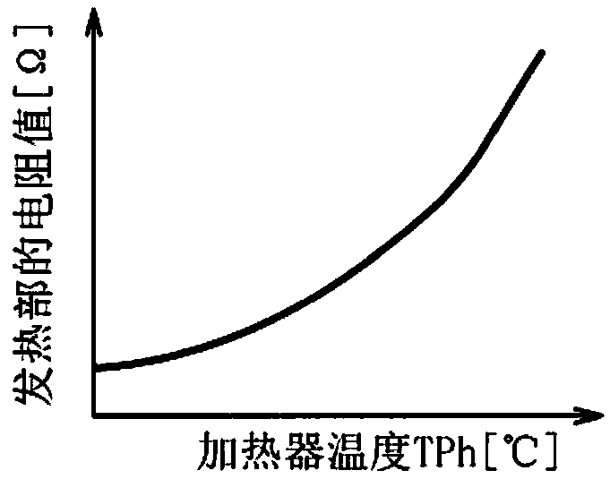
[0111] In this embodiment, as figure 2 The power supply 16 is a variable voltage power supply capable of changing the power supply voltage step by step. Then, the heater control device 14 continuously changes the power supply voltage which is the output voltage of the power supply 16 . Specifically, as Figure 10 As shown, the heater control device 14 varies the power supply voltage within a range from 0 V to a predetermined constant voltage Vc. The constant voltage Vc refers to a voltage maintained at the power supply voltage after the heater temperature TPh is saturated. In addition, the constant voltage Vc is experimentally set in advance so that the current value of the electric heater 12 can be maintained at a value below the current upper limit ALu and close to the current upper limit ALu after the heater temperatu...
PUM
 Abstract
Description
Claims
Application Information
 - R&D Engineer
- R&D Manager
- IP Professional
- Industry Leading Data Capabilities
- Powerful AI technology
- Patent DNA Extraction
Browse by: Latest US Patents, China's latest patents, Technical Efficacy Thesaurus, Application Domain, Technology Topic.
© 2024 PatSnap. All rights reserved.Legal|Privacy policy|Modern Slavery Act Transparency Statement|Sitemap