
A prefabricated wall and its installation method

A prefabricated and wall-mounted technology, which is applied in the processing of walls, buildings, and building materials, can solve problems such as high labor intensity, low installation efficiency, and noise pollution, and achieve the effect of convenient sliding operation and overcoming low installation efficiency

Active Publication Date: 2020-10-27
BEIJING NEW BUILDING MATERIALS PLC
View PDF6 Cites 0 Cited by
  • Summary
  • Abstract
  • Description
  • Claims
  • Application Information

AI Technical Summary

Problems solved by technology

[0004] The technical problem solved by this application is to provide a prefabricated wall and its installation method, which can effectively overcome the defects of low installation efficiency, high labor intensity and noise pollution in the existing wall.

Method used


Image

  • A prefabricated wall and its installation method
  • A prefabricated wall and its installation method
  • A prefabricated wall and its installation method

Examples


Embodiment 1

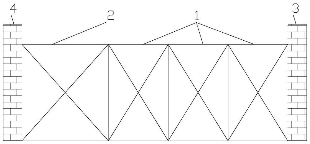
[0065] like figure 1 As shown, Embodiment 1 of the present invention provides a prefabricated wall, including a first wall unit 1 and a second wall unit 2; the head end of the first wall unit 1 is used to connect the head end of the prefabricated wall The building structure wall at 3, the end of the first wall unit 1 is connected to the head of the second wall unit 2, and the tail of the second wall unit 2 is connected to the building structure wall at the end of the prefabricated wall 4.

[0066] In the specific operation, the installation of the main body of the prefabricated wall can be realized through the setting of the above-mentioned first wall unit 1; the installation of the wall in the final non-standard size space can be realized through the setting of the above-mentioned second wall unit 2.

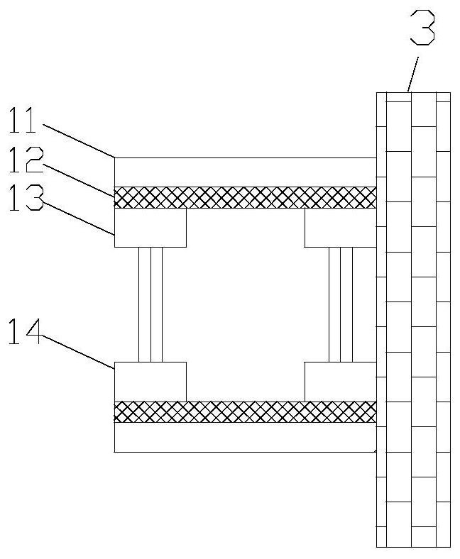
[0067] like figure 2 As shown, the first wall unit 1 in this embodiment includes a symmetrically arranged first wall component and a second wall component, and the first wal...

Embodiment 2

[0106] Embodiment 2 of the present invention provides an installation method applied to the prefabricated wall of Embodiment 1, including:

[0107] The head end of the first wall unit is connected to the building structure wall at the head end of the prefabricated wall;

[0108] The fixed wall mechanism of the second wall unit connects the end of the first wall unit, such as Figure 13 Slide the sliding wall mechanism out from the inside of the fixed wall mechanism as shown; Figure 14 , 15 As shown, the end of the sliding wall mechanism close to the end of the prefabricated wall is cut off the gypsum board with a predetermined width; wherein, the width of the remaining gypsum board is equal to the distance between the fixed wall mechanism and the wall surface of the house structure at the end of the prefabricated wall. width between

[0109] The sliding wall mechanism slides to the wall of the building structure, such as Figure 16 As shown, the ends of the telescoping su...


PUM


Abstract

Disclosed is an assembly-type wall, comprising a first wall unit (1) and a second wall unit (2), wherein a first end of the first wall unit (1) is used for connecting to a house structure wall (3) at a first end of the assembly-type wall, a second end of the first wall unit (1) is connected to a first end of the second wall unit (2), and a second end of the second wall unit (2) is connected to a house structure wall (4) at a second end of the assembly-type wall; the second wall unit (2) comprises a fixed wall mechanism (21) and a slidable wall mechanism (22), and a first end of the fixed wall mechanism (21) is connected to the second end of the first wall unit (1); an inner side of the fixed wall mechanism (21) is provided with a sliding rail (211), the slidable wall mechanism (22) is provided on the sliding rail (211), and the sliding direction of the sliding rail (211) is parallel with the wall direction of the fixed wall mechanism (21); and an inner side of the slidable wall mechanism (22) is provided with a telescopic support rod (221) used for adjusting the thickness of the slidable wall mechanism (22).The assembly-type wall can realise wall installation in non-standard sized spaces, thereby increasing installation efficiency and reducing labour intensity and noise pollution.

Description

technical field [0001] This application relates to but not limited to the technical field of construction, especially a prefabricated wall and its installation method. Background technique [0002] In the prior art, prefabricated walls are all provided with standard sizes, such as standard sizes such as wall unit widths of 400mm, 600mm, and 1200mm; however, in the actual construction process, the space size in the house is not an integer multiple of the standard size. This will directly result in the last wall element being a non-standard sized wall element. [0003] At present, the installation of the last wall unit needs to be handmade on site, and different keels, plasterboards, etc. are made according to different sizes; the processing operation on site will bring many defects, such as high labor intensity, low installation efficiency, noise pollution and other defects . Contents of the invention [0004] The technical problem solved by this application is to provide...

Claims


Application Information

Patent Timeline
Patent Type & Authority Patents(China)
IPC IPC(8): E04B2/00E04G21/14
CPCE04B2/00E04G21/14E04B2/82
Inventor 何亮王鹏起谭丹君王莹尹东杰
Owner BEIJING NEW BUILDING MATERIALS PLC
Learn More