Chain type linear lamp

A linear lamp and chain-type technology, which is applied in the direction of lighting devices, electric light sources, and parts of lighting devices, can solve the problems of single shape, poor decorative effect, poor lighting effect, etc., and achieve high practicability, simple operation, and design reasonable effect

Pending Publication Date: 2019-03-05
ROMNEY OPTO ELECTRONICS SYST TECH GUANGDONG CO LTD
View PDF0 Cites 6 Cited by
  • Summary
  • Abstract
  • Description
  • Claims
  • Application Information

AI Technical Summary

Problems solved by technology

[0003] With the development of the times and the advancement of science and technology, more and more types of lamps have emerged, but th

Method used


Image

  • Chain type linear lamp
  • Chain type linear lamp
  • Chain type linear lamp

Examples


Embodiment 1

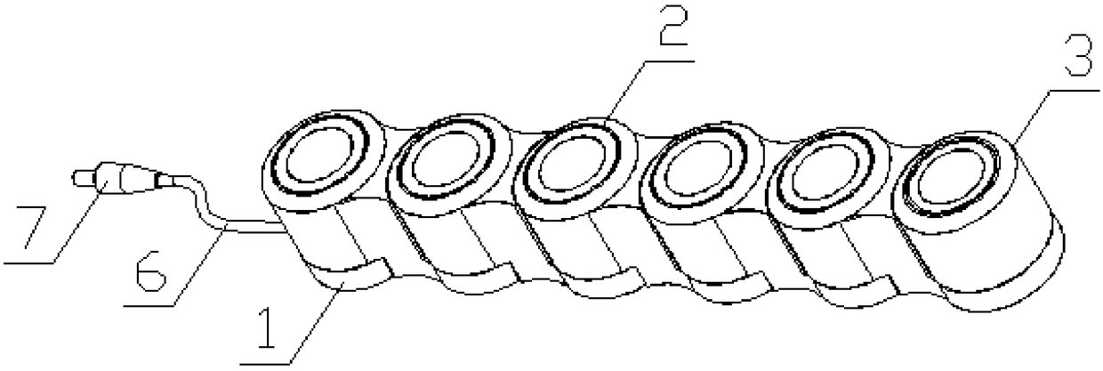
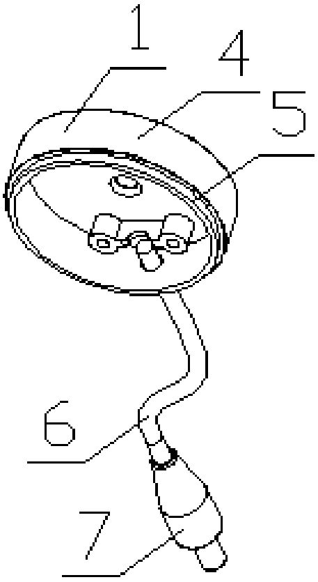
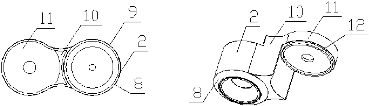
[0022] Embodiment 1: A chained linear lamp, comprising a lampstand 1 for placing a connecting mechanism 2, the lampstand 1 is provided with a connecting mechanism 2, and the connecting mechanism 2 is provided with a lighting mechanism 3, and the lampstand 1 includes The lampstand body 4, the lampstand body 4 is provided with a mounting post 5, the side of the lampstand body 4 is provided with a wire 6, and the end of the wire 6 is provided with a plug 7 for connecting a power supply, and the connection mechanism 2 includes The first main light 8, the bottom of the first main light 8 is provided with a first card slot 9, the side of the first main light 8 is provided with a connecting piece 10, the side of the connecting piece 10 is provided with a connecting platform 11, the The connection platform 11 is provided with a connection boss 12 , the lighting mechanism 3 includes a second main light 13 , and a second card slot 14 is provided at the bottom of the second main light 13 ...

Embodiment 2

[0024] Embodiment 2: The difference from Embodiment 1 is: a chain linear lamp, including a lamp stand 1, a connecting mechanism 2 is provided on the lamp stand 1, and a lighting mechanism 3 is arranged on the top of the connecting mechanism 2, and the lamp stand 1 Including the lampstand body 4, the lampstand body 4 is provided with a mounting post 5, the side of the lampstand body 4 is provided with a wire 6, the end of the wire 6 is provided with a plug 7, the connecting mechanism 2 includes a connecting body 15, The top of the connecting body 15 is provided with a first annular boss 16 and a second annular boss 17, the connecting body 15 is provided with a first annular groove 18, the lighting mechanism 3 includes a lamp 19, and the bottom of the lamp 19 A second annular groove 20 is provided.

[0025] Both the connecting mechanism 2 and the lighting mechanism 3 are provided with a plurality, and the installation boss 5 and the second annular boss 17 are matched with the fi...


PUM


Abstract

The invention discloses a chain type linear lamp. The chain type linear lamp comprises a lamp stand. A first body is arranged on the lamp stand, and a second body is arranged on the first body. The lamp stand comprises a lamp stand body, a mounting convex column is arranged on the lamp stand body, the lamp stand body is provided with a wire, and a plug is arranged at the end of the wire. The firstbody comprises first main lamps, first clamping grooves are formed in the bottoms of the first main lamps, connecting parts are arranged on the side faces of the first main lamps, connecting tables are arranged on the side faces of the connecting parts, and connecting convex columns are arranged on the connecting tables. Any two of the lamp stand, the first body and the second body can freely rotate while the lamp stand, the first body and the second body are mutually connected through the mounting convex column, the first clamping grooves, the connecting convex columns and second clamping grooves, thus, the appearance of the chain type linear lamp can change according to the practical situation of a user, and the chain type linear lamp has the beneficial effects of being reasonable in design, easy to operate and the like, and has high practicality.

Description

technical field [0001] The invention relates to the technical field of lighting equipment, in particular to a chained linear lamp. Background technique [0002] Where there is light, there is human civilization. Tens of thousands of years ago, human beings knew how to use natural fire to keep out the cold, barbecue and lighting. From stone lamps to bronze lamps, ceramic lamps to modern electric lamps, the historical changes of lamps and lanterns have imprinted a profound imprint of the times, and are also the epitome of social economy and culture. [0003] With the development of the times and the progress of science and technology, more and more types of lamps also appear thereupon, but there are some problems in the existing lamps, such as the common defects of single shape, poor lighting effect and poor decorative effect. [0004] Therefore, it is necessary to invent a chain type linear lamp to solve the above problems. Contents of the invention [0005] The object of...

Claims


Application Information

Patent Timeline
IPC IPC(8): F21S4/00F21V21/005
CPCF21S4/00F21V21/005
Inventor 彭银水
Owner ROMNEY OPTO ELECTRONICS SYST TECH GUANGDONG CO LTD
Why Eureka
Try Eureka