Structure of filter subassembly in air cleaner

A technology for filter components and air purifiers, applied in the fields of dispersed particle filtration, chemical instruments and methods, air conditioning systems, etc., can solve problems such as not easy disassembly, difficult filter replacement or maintenance operations, etc., to prevent pollution and improve purchases. Desire, the effect of raising awareness of use

Inactive Publication Date: 2006-02-01
LG ELECTRONICS (TIANJIN) APPLIANCES CO LTD
View PDF0 Cites 7 Cited by
  • Summary
  • Abstract
  • Description
  • Claims
  • Application Information

AI Technical Summary

Problems solved by technology

[0017] The disadvantage of the above-mentioned existing air cleaner 10 is: the filter assembly 18 is fixedly arranged on one side of the air cleaner 10, so it is not easy to disassemble, which brings great difficulties to the replacement or maintenance of the filter.

Method used


Image

  • Structure of filter subassembly in air cleaner
  • Structure of filter subassembly in air cleaner
  • Structure of filter subassembly in air cleaner

Examples


Embodiment Construction

[0068] The present invention is described in further detail below in conjunction with the accompanying drawings and specific embodiments:

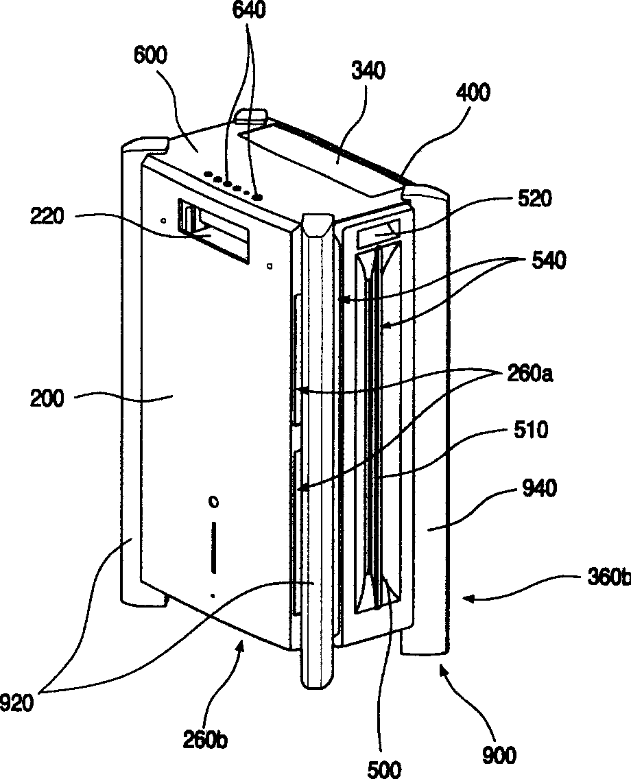
[0069] image 3 It is a three-dimensional schematic diagram of an air purifier adopting the filter assembly structure of the air purifier of the present invention; Figure 4 It is a schematic diagram of the exploded structure of the air purifier adopting the filter assembly structure of the air purifier of the present invention; Figure 5 It is a structural schematic diagram of the front frame of the air purifier adopting the filter assembly structure of the air purifier of the present invention; Image 6 It is a schematic structural diagram when a front panel is installed on the front frame of the air purifier using the filter assembly structure of the air purifier of the present invention; Figure 7 It is a three-dimensional schematic diagram of the filter assembly structure of the air purifier of the present invention; Figure 8 It i...


PUM


Abstract

The present invention discloses a filter component structure of air purifier. It includes filter for purifying air, filter external shell for placing filter, filter guide frame for inserting and mounting filter external shell and filter guide frame channel cover placed on one side surface of filter guide frame.

Description

technical field [0001] The invention relates to an air purifier, in particular to a filter assembly structure of the air purifier. Background technique [0002] In recent years, air pollution has become more and more serious. The air often contains dust and foreign objects that are harmful to the human body. Direct inhalation of these polluted air will seriously affect people's health. In order to solve the above problems, people have developed various air purifiers that can filter out dust and foreign matter in the air. [0003] figure 1 Show the three-dimensional intent of the existing air purifier; figure 2 It is a schematic diagram of the exploded structure of the existing air purifier filter. like figure 1 and figure 2 As shown, the housing of the existing air purifier 10 includes: a front panel 12 forming a front appearance, a side panel 14 forming a side appearance, a rear panel (not shown) forming a rear appearance, and forming a top appearance. Top panel 16....

Claims


Application Information

Patent Timeline
Patent Type & Authority Applications(China)
IPC IPC(8): F24F3/16B01D46/10
Inventor 徐正尚洪宁基
Owner LG ELECTRONICS (TIANJIN) APPLIANCES CO LTD
Why Eureka
Try Eureka