A cable shovel

A technology for shoveling boards and cables, applied in the direction of lifting devices, etc., can solve problems such as cable trays and loading, and achieve the effects of simple structure, convenient loading/unloading of cables, and high work efficiency

Active Publication Date: 2018-08-14
安徽腾飞特种电缆科技有限公司
View PDF8 Cites 0 Cited by
  • Summary
  • Abstract
  • Description
  • Claims
  • Application Information

AI Technical Summary

Problems solved by technology

Obviously, it also cannot solve the problem of conveniently loading and unloading the cable tray and not damaging the cables in the process

Method used


Image

  • A cable shovel
  • A cable shovel
  • A cable shovel

Examples


Embodiment 1

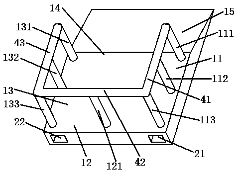
[0026] please see figure 1 , a cable shovel, is characterized in that it comprises a pressure-resistant plate, a slope 15 connected to the front side 14 of the pressure-resistant plate, three first-type retaining strips of equal height installed on the right side surface 11 of the pressure-resistant plate, Three second-type retaining bars with equal heights installed on the left side surface 13 of the pressure-resistant plate, three equal-height third-type retaining bars installed on the pressure-resistant plate rear surface 12, the first limit bar 41, the second limit bar Position strip 43 and the third limit strip 42; the first limit strip is located at the upper end of the first type of dam strip and connects the first type of dam strip together, and the second limit strip is positioned at the upper end of the second type of dam strip and connects the second The third limit bar is located at the upper end of the third type bar and the third bar is connected together, one en...

Embodiment 2

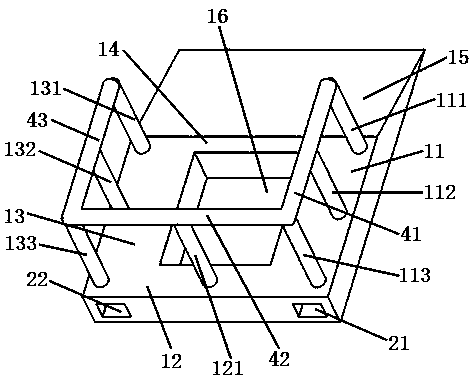
[0029] please see figure 2, a cable shovel, is characterized in that it comprises a pressure-resistant plate, a slope 15 connected to the front side 14 of the pressure-resistant plate, three first-type retaining strips of equal height installed on the right side surface 11 of the pressure-resistant plate, Three second-type retaining bars with equal heights installed on the left side surface 13 of the pressure-resistant plate, three equal-height third-type retaining bars installed on the pressure-resistant plate rear surface 12, the first limit bar 41, the second limit bar Position strip 43 and the third limit strip 42; the first limit strip is located at the upper end of the first type of dam strip and connects the first type of dam strip together, and the second limit strip is positioned at the upper end of the second type of dam strip and connects the second The third limit bar is located at the upper end of the third type bar and the third bar is connected together, one en...

Embodiment 3

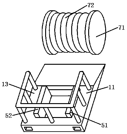
[0032] please see image 3 , and refer to figure 1 and figure 2 , a cable shovel plate, basically the same as the implementation example 2, except that: the right side surface 11 of the pressure-resistant plate has a first limiting plate 51 protruding upward, and the first limiting plate is located on the right side of the middle groove. There is a gap between the first limiting plate and the first type of bar; the left side surface 13 of the pressure-resistant plate has a second limiting plate 52 protruding upwards, and the second limiting plate is located on the left side of the middle groove. On the side, there is a gap between the second limiting plate and the second type of bar.

[0033] When shipping the cable reel, push the cable reel up the pressure-resistant plate along the slope, so that the side plate 71 of the cable reel enters the gap between the limit plate and the retaining bar, and the shovel of the forklift enters the first groove and the second groove. Tw...


PUM


Abstract

The invention belongs to the technical field of cables and conveyance, and particularly relates to a cable insertion board. The cable insertion board comprises a pressure-resisting flat plate, a slope, a first type of barrier strips, a second type of barrier strips, a third type of barrier strips, first limiting strips, second limiting strips and third limiting strips, wherein the first limiting strips are positioned at the upper ends of the first type of barrier strips; the first type of barrier strips are connected to one another through the first limiting strips; the second limiting strips are positioned at the upper ends of the second type of barrier strips; the second type of barrier strips are connected to one another by the second limiting strips; the third limiting strips are positioned at the upper ends of the third type of barrier strips; the third type of barrier strips are connected to one another by the third limiting strips; one end of each third limiting strip is connected with one end of the corresponding first limiting strip; the other end of each third limiting strip is connected with one end of the corresponding second limiting strip; and a groove capable of accommodating a shovel of a forklift is formed in the pressure-resisting flat plate in the direction from the rear surface of the pressure-resisting flat plate to the front surface of the pressure-resisting flat plate. The cable insertion board has the advantages that the cable insertion board is simple in structure, easy to manufacture and excellent in using effect and is safe, labor can be saved, cables are loaded or unloaded conveniently, a cable reel is not easy to damage, and the work efficiency is high.

Description

technical field [0001] The invention belongs to the technical field of cables and transportation, and in particular relates to a cable shovel. Background technique [0002] With the great development of industrialization, the use of cables is increasing day by day. Cables with large diameter or length are usually coiled on the reel, and the weight of such cables is relatively heavy. Generally speaking, they need to be transported by a forklift Attach to or remove from the vehicle. Since the cable reel is usually composed of two cylindrical thin discs arranged parallel to each other, a cylinder connected to the two discs and other accessories, the cable is wound on the cylinder of the reel, when loading and unloading the cable reel , It is not allowed to damage the cable, so when loading and unloading, it is usually parallel to the axis of the disc and the shovel is below the disc. For vehicles that are open on all sides, when the area of ​​the site is sufficient, the above...

Claims


Application Information

Patent Timeline
Patent Type & Authority Patents(China)
IPC IPC(8): B66F9/12
CPCB66F9/12
Inventor 沈宇杰
Owner 安徽腾飞特种电缆科技有限公司
Why Eureka
Try Eureka