
Magnetic assembly structure

A technology of assembly structure and magnetic force, applied in the direction of fixtures, mechanical equipment, etc., can solve problems such as unsightly appearance and inconvenient disassembly

Inactive Publication Date: 2020-06-02
上海阿为特精密机械股份有限公司
View PDF0 Cites 0 Cited by
  • Summary
  • Abstract
  • Description
  • Claims
  • Application Information

AI Technical Summary

Problems solved by technology

[0003] The technical problem to be solved by the present invention is: the cover plate parts are locked and fixed by screws and assembled into one, which is inconvenient to disassemble and unsightly

Method used


Image

  • Magnetic assembly structure
  • Magnetic assembly structure
  • Magnetic assembly structure

Examples


Embodiment

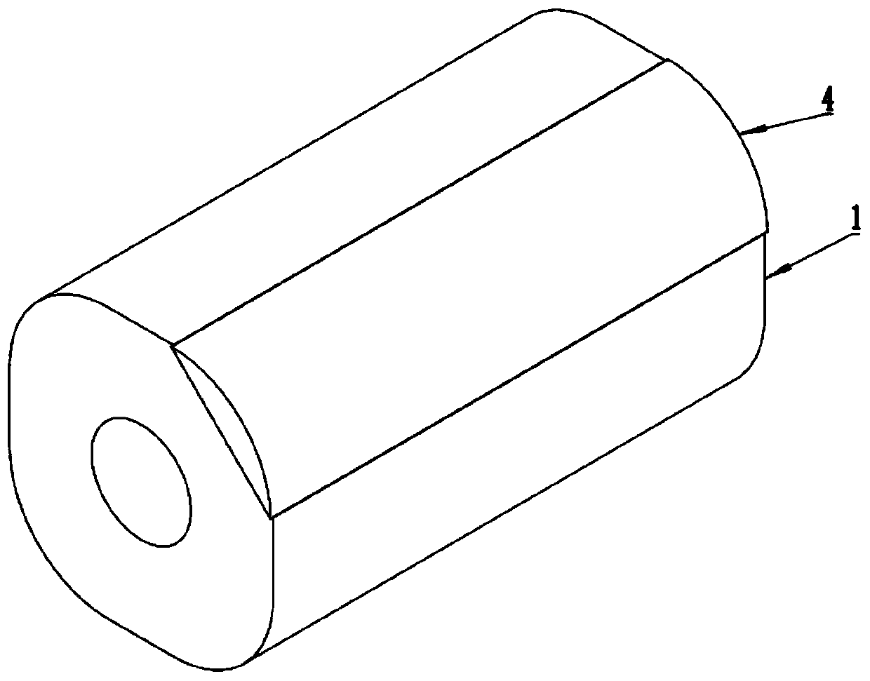
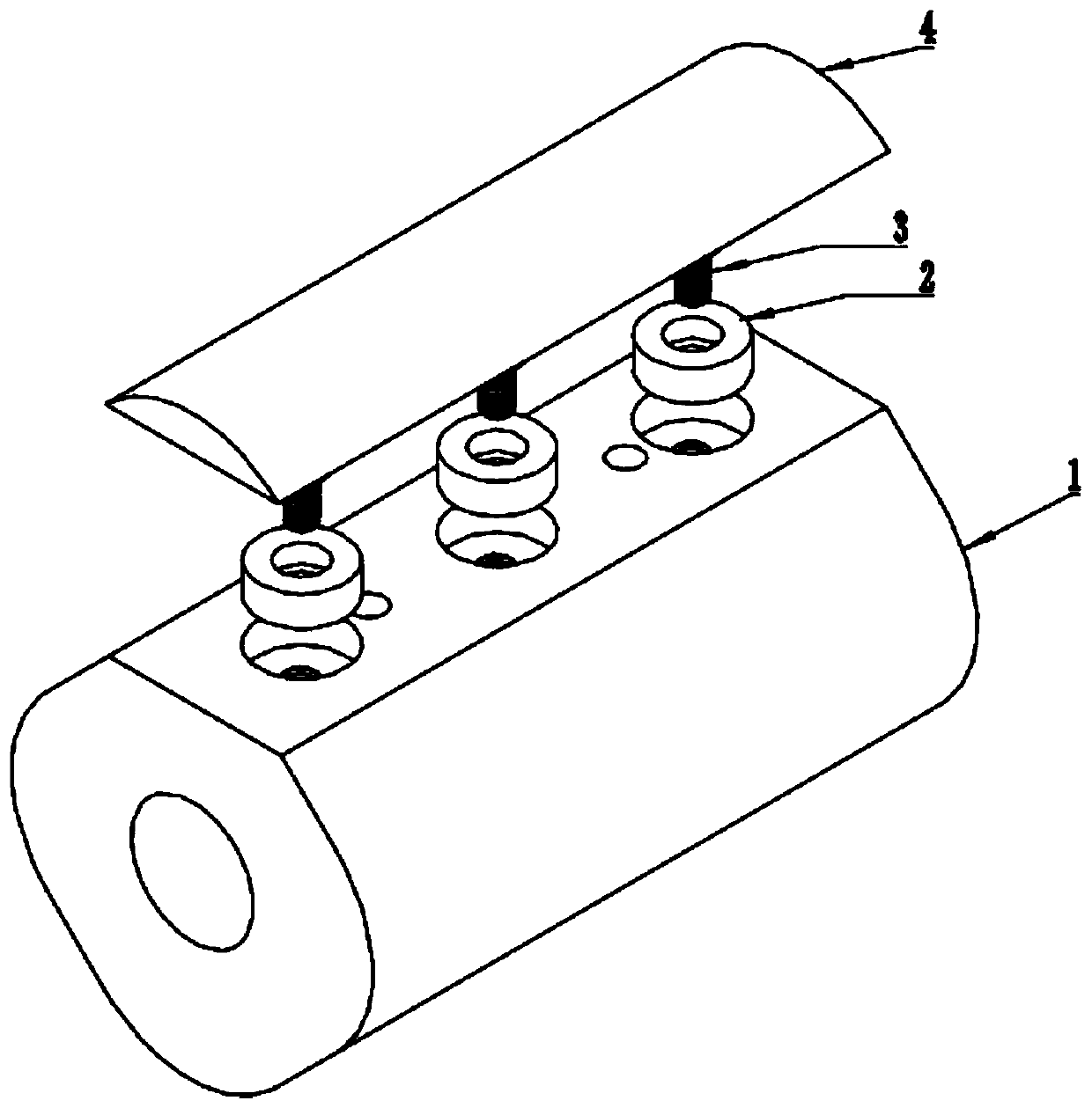
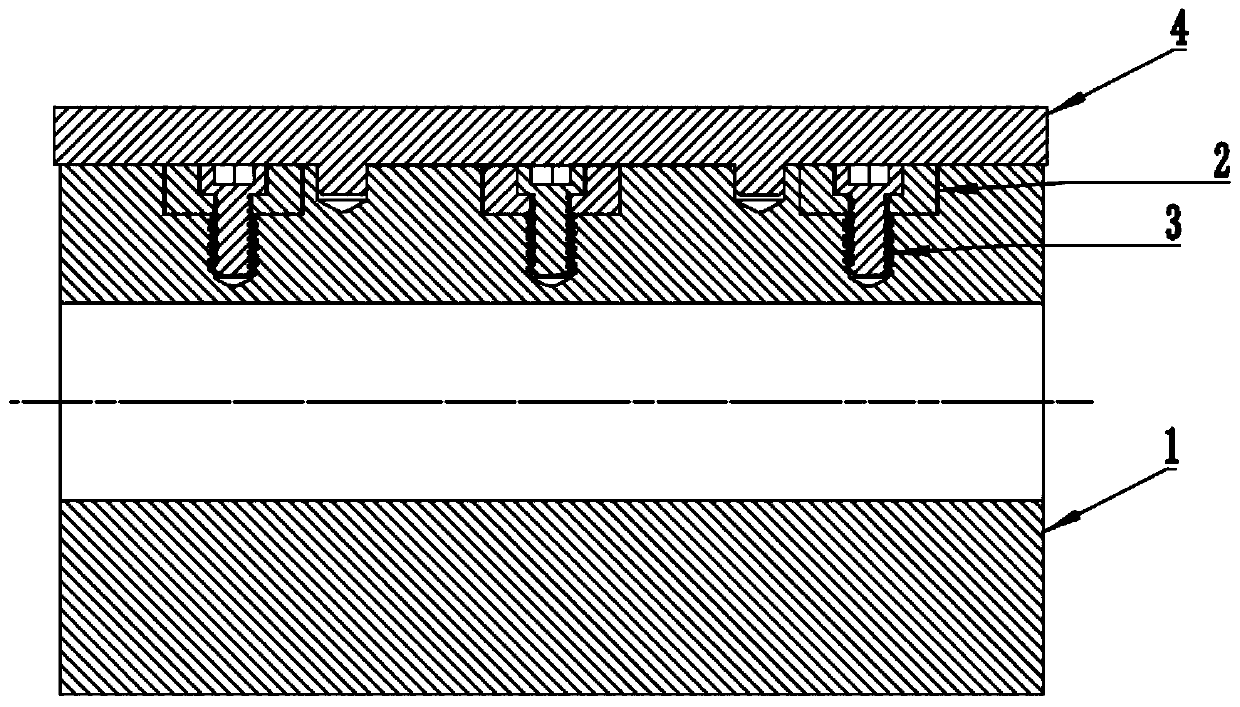
[0014] Such as Figure 1-4 As shown, it is a magnetic assembly structure provided by the present invention. The main body 1 and the cover 4 are two parts to be assembled. Put the magnet 2 into the groove on the top of the main body 1 and fix it with screws 3, and then put the cover 4 Just align the positioning pin structure at the bottom with the pin hole on the top of the main body 1 and insert it. In design, the outer edge of the cover 4 is slightly protruding than the outer edge of the main body 1, which is convenient for disassembly. Wherein, the cover 4 is made of magnetic material or is provided with magnetic material parts inside, so that the cover 4 becomes a magnet that can be attracted by the magnet 2 .


PUM


Abstract

The invention discloses a magnetic assembly structure. The magnetic assembly structure is characterized in that a magnet fixed at the top of a main body through screws is included, and a cover assembled above the main body is made of a magnetic material or is internally provided with a magnetic material part. The magnetic assembly structure can be used for any light equipment, parts and cover plates with requirements for appearance design, fixation through screws is not needed, and the magnetic assembly structure can be assembled to a designated position and is convenient to assemble and disassemble, attractive in appearance and high in universality.

Description

technical field [0001] The invention relates to a magnetic assembly structure, which belongs to the technical field of mechanical processing equipment. Background technique [0002] At present, the general assembly of parts on the market is to connect the two parts into a whole by screw locking. The disadvantage of this structure is that the assembly efficiency is low, and it is inconvenient to disassemble, and the appearance is not beautiful because of the need for screw holes. . Contents of the invention [0003] The technical problem to be solved by the present invention is: the cover plate parts are locked and fixed by screws and assembled into one body, which is inconvenient to disassemble and unsightly. [0004] In order to solve the above problems, the present invention provides a magnetic assembly structure, which is characterized in that it includes a magnet fixed on the top of the main body by screws, and the cover assembled above the main body is made of magnet...

Claims


Application Information

Patent Timeline
Patent Type & Authority Applications(China)
IPC IPC(8): F16B1/00
CPCF16B1/00F16B2200/83
Inventor 李露平熊朝林岳卫民李培英陈小勇周献争高福喜庞柯
Owner 上海阿为特精密机械股份有限公司
Learn More