
Fluid injection valve

A fluid injection and flow channel technology, applied in the field of liquid micro-ejection devices, can solve the problems of difficult operation and long time consumption, and achieve the effects of less difficult operation, quick correction operation, and convenient and quick debugging operation.

Pending Publication Date: 2019-03-08
深圳市锐德精密科技有限公司
View PDF0 Cites 3 Cited by
  • Summary
  • Abstract
  • Description
  • Claims
  • Application Information

AI Technical Summary

Problems solved by technology

[0004] The technical problem to be solved by the present invention is to provide a fluid injection valve, aiming at the problem that the debugging structure of the lower end part of the fluid injection valve in the prior art is difficult and takes a long time

Method used


Image

  • Fluid injection valve

Examples


Embodiment Construction

[0015] In order to make the object, technical solution and advantages of the present invention clearer, the present invention will be further described in detail below in conjunction with the accompanying drawings and embodiments. It should be understood that the specific embodiments described here are only used to explain the present invention, not to limit the present invention.

[0016] In the description of the present invention, it should be noted that the terms "center", "upper", "lower", "left", "right", "vertical", "horizontal", "inner", "outer" etc. The indicated orientation or positional relationship is based on the orientation or positional relationship shown in the drawings, and is only for the convenience of describing the present invention and simplifying the description, rather than indicating or implying that the referred device or element must have a specific orientation, or in a specific orientation. construction and operation, and therefore cannot be constru...


PUM


Abstract

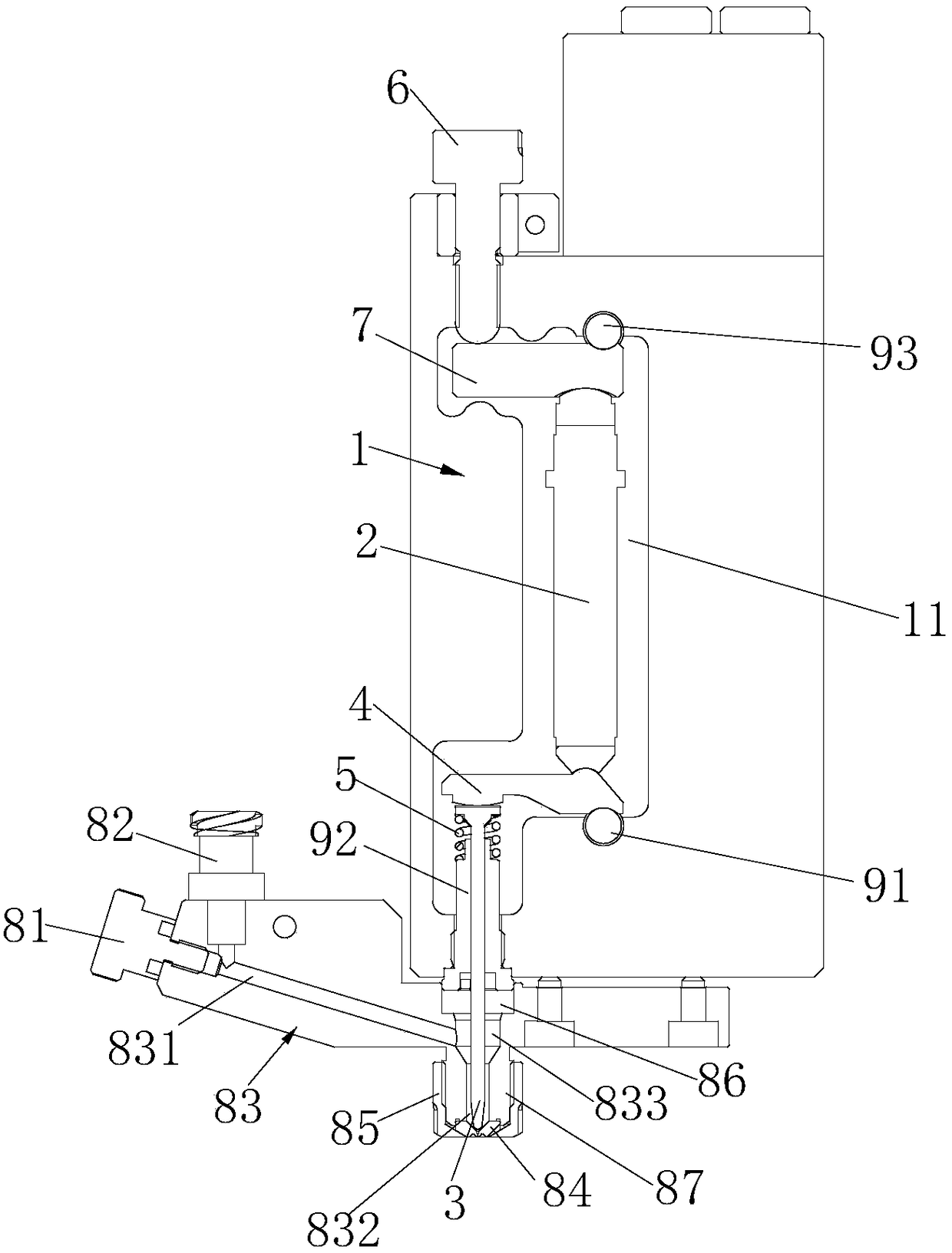
The invention provides a fluid injection valve and is applied to the field of liquid trace injection devices. Compared with an existing fluid injection valve, an upper end lever and a lower end leverwhich can swing up and down are arranged in the fluid injection valve, the top of a valve body is provided with an adjusting screw, the adjusting screw is screwed, and the adjusting screw can move upand down. When the adjusting screw moves up and down, the bottom of the adjusting screw presses the upper end lever, so that the upper end lever is inclined relative to the horizontal direction, the angle range of the horizontal inclination of the upper end lever is large, and the angle range of the swing of the lever at the lower end of piezoelectric ceramic is directly influenced. If displacement deviation occurs in the lower end lever, only the adjusting screw needs to be screwed, the angle range of the swing of the lower end lever can be adjusted, and therefore the up-down displacement deviation of the lower end lever can be corrected. Therefore, according to the fluid injection valve, the rapid correcting operation can be realized only by screwing the adjusting screw, and the operation difficulty is low. Meanwhile, the adjusting screw is located at the top of the valve body, and the periphery of the adjusting screw is free of objects, so that the debugging operation is convenientand rapid.

Description

technical field [0001] The invention belongs to the field of liquid micro-injection devices, in particular to a fluid injection valve. Background technique [0002] A fluid injection valve is a device that can eject extremely small amounts of liquid material at high speed, which can be applied to microelectronic packaging. The fluid injection valve can be divided into pneumatic type and piezoelectric type according to different power sources. Piezoelectric injection valves utilize the inverse piezoelectric effect of piezoelectric materials, have high injection frequency, simple equipment structure, and injection can obtain glue dots with a diameter as small as 0.2mm; on the other hand, the piezoelectric structure has high control precision and can Improve jet dispensing quality. [0003] During a long period of operation, the lever that directly hits the striker will have a displacement deviation in the up and down direction, so it needs to be debugged. The current fluid ...

Claims


Application Information

Patent Timeline
IPC IPC(8): B05B17/06
CPCB05B17/0607
Inventor 刘耀鹏
Owner 深圳市锐德精密科技有限公司
Learn More