
Electric equipment interface and electric equipment

A technology for electrical equipment and power distribution equipment, applied in electrical components, circuit devices, emergency protection circuit devices, etc., can solve problems such as safety accidents, difficulty in distinguishing power distribution sockets, and easy insertion of electrical appliances, and achieve the effect of avoiding failure.

Inactive Publication Date: 2019-03-08
GREE ELECTRIC APPLIANCES INC
View PDF3 Cites 2 Cited by
  • Summary
  • Abstract
  • Description
  • Claims
  • Application Information

AI Technical Summary

Problems solved by technology

However, there is currently no standard specification for the DC voltage level of household power distribution, and there are different power voltage levels proposed by various manufacturers for different electrical appliances, such as 400VDC, 200VDC, 48VDC, 24VDC, etc.
In addition, some electrical appliances currently used through AC adapters, such as mobile phone chargers 5VDC, sphygmomanometers 6VDC, wireless routers 9VDC, laptop computers 12VDC, photography lights 15VDC, active speakers, barcode printers 24VDC, etc., are actually DC appliances, but the voltage Levels are also defined in disorder. If a full DC micro-grid is used for home applications, there will be multiple brands of electrical appliances with multiple voltage levels, and multiple types of electrical appliances with multiple voltage levels. As a result, there are many power distribution sockets that are difficult to distinguish, and electrical appliances are easy to be plugged in wrongly and fail. even lead to safety accidents

Method used


Image

  • Electric equipment interface and electric equipment
  • Electric equipment interface and electric equipment
  • Electric equipment interface and electric equipment

Examples


Embodiment Construction

[0037] In order to make the purpose, technical solution and advantages of the present application clearer, the implementation manners of the present application will be further described in detail below in conjunction with the accompanying drawings.

[0038] Reference will now be made in detail to the exemplary embodiments, examples of which are illustrated in the accompanying drawings. When the following description refers to the accompanying drawings, the same numerals in different drawings refer to the same or similar elements unless otherwise indicated. The implementations described in the following exemplary embodiments do not represent all implementations consistent with this application. Rather, they are merely examples of apparatuses and methods consistent with aspects of the present application as recited in the appended claims.

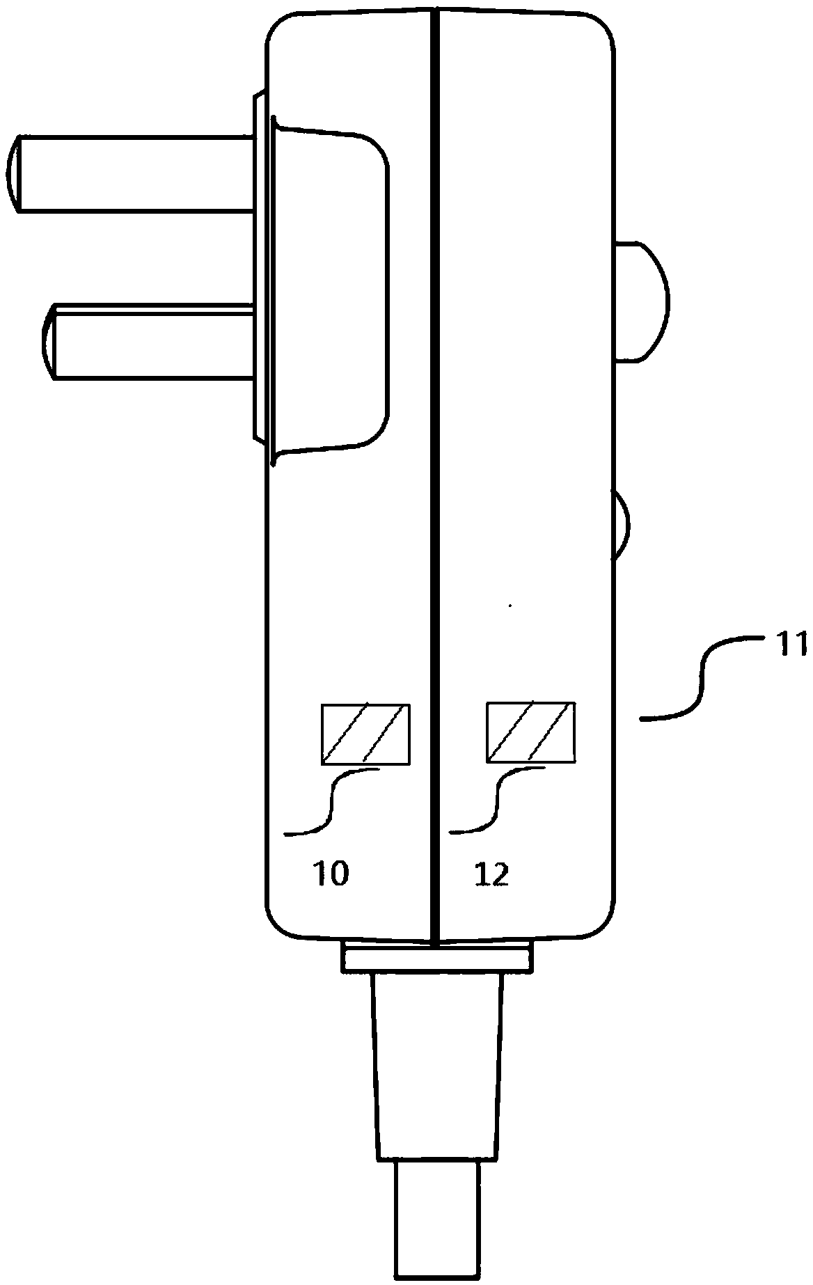
[0039] figure 1 is a schematic diagram of an electrical device interface shown according to an exemplary embodiment, such as figure 1 As...


PUM


Abstract

The invention provides an electric equipment interface and electric equipment. The electric equipment interface comprises an electric parameter detection module and a control module, wherein the electric parameter detection module is used for detecting whether electric parameters provided by a power distribution equipment interface are matched with rated operation electric parameters of the electric equipment when the electric equipment interface is connected with the power distribution equipment interface or not; and the control module is used for controlling a power supply circuit to turn onso as to supply power for the electric equipment through the electric equipment interface when the electric parameters provided by the power distribution equipment interface are matched with the rated operation electric parameters of the electric equipment. The electric equipment interface has an electric parameter detection decision-making function, and when an electric appliance is in a specific distribution voltage or current range, electricity can be saved, so that the problem that the electric appliance is plugged by mistake to lose efficacy or even cause safety accidents is avoided.

Description

technical field [0001] The present application relates to the field of electronic appliances, and in particular to an electrical equipment interface and electrical equipment. Background technique [0002] In home application of DC micro-grid, when the DC line is distributed to the room, the DC interface, that is, the DC plug and socket, will be used to conveniently plug in and pull out the DC equipment in the home. However, there is currently no standard specification for the DC voltage level of household power distribution, and there are different power voltage levels proposed by various manufacturers for different electrical appliances, such as 400VDC, 200VDC, 48VDC, 24VDC and so on. In addition, some electrical appliances currently used through AC adapters, such as mobile phone chargers 5VDC, sphygmomanometers 6VDC, wireless routers 9VDC, laptop computers 12VDC, photography lights 15VDC, active speakers, barcode printers 24VDC, etc., are actually DC appliances, but the vo...

Claims


Application Information

Patent Timeline
Patent Type & Authority Applications(China)
IPC IPC(8): H02J4/00H02H11/00
CPCH02H11/00H02H11/006H02J4/00
Inventor 袁金荣赵志刚蒋世用李秋莲李向前
Owner GREE ELECTRIC APPLIANCES INC
Learn More