
Switching device, electronic detection system and control method

A technology of a switching device and a control method, which is applied to the components of the connecting device, the connection/disconnection of the connecting device, and the coupling device, etc., can solve the problems of labor-consuming, error-prone test wire insertion and extraction, and low test success rate.

Pending Publication Date: 2020-08-07
北京送变电有限公司 +1
View PDF0 Cites 1 Cited by
  • Summary
  • Abstract
  • Description
  • Claims
  • Application Information

AI Technical Summary

Problems solved by technology

[0004] In view of this, the embodiment of the present invention provides an adapter device, an electronic detection system and a control method, the main purpose of which is to solve the problem that the 10KV vacuum circuit breaker in the prior art is prone to errors in plugging and unplugging test lines when performing multiple tests and tests. The plugging and unplugging needs to be operated by a special person, resulting in low test success rate, labor-intensive and low-efficiency problems

Method used


Image

  • Switching device, electronic detection system and control method
  • Switching device, electronic detection system and control method
  • Switching device, electronic detection system and control method

Examples


Embodiment 1

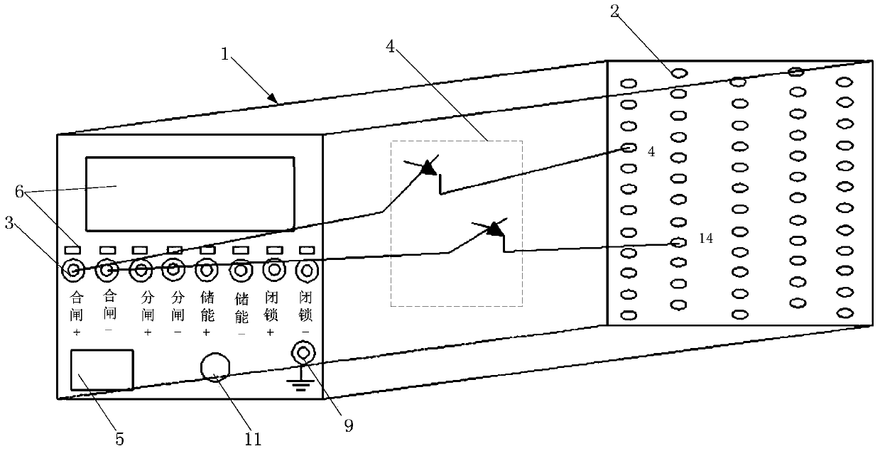
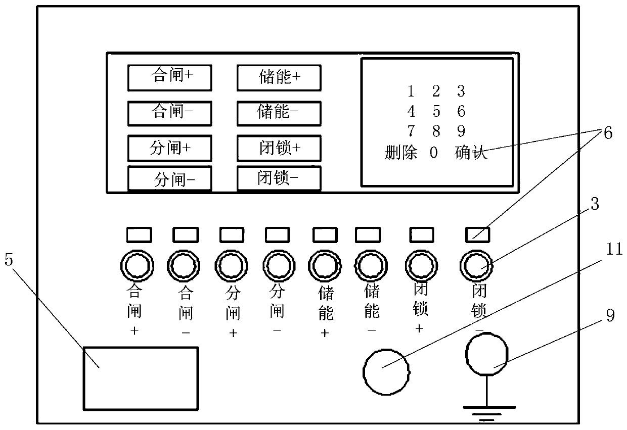
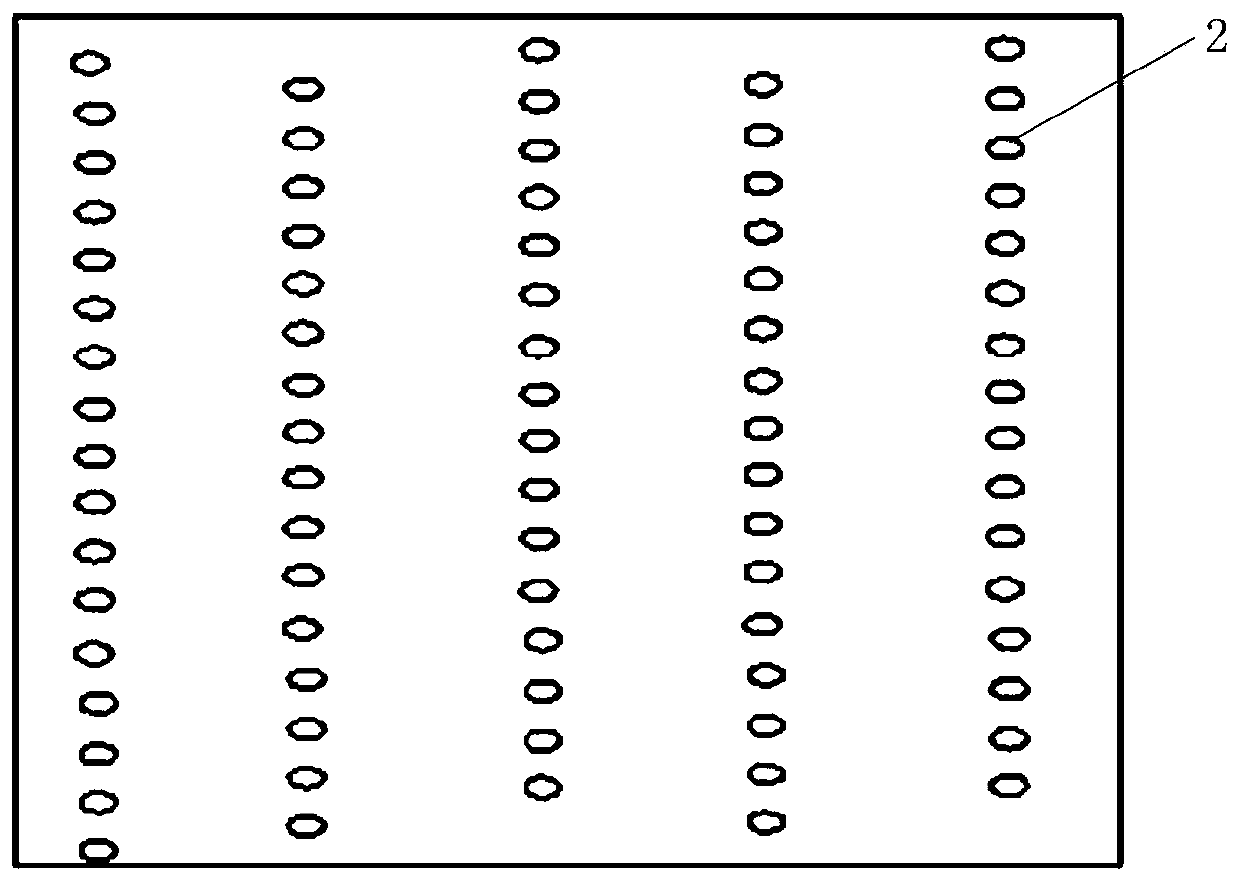
[0059] Reference attached figure 1 , attached figure 2 and attached image 3 , an adapter device provided by the present invention is connected between a vacuum circuit breaker 7 and a detection device 8, and includes a housing 1, a plurality of first electrical connection terminals 2, a plurality of second electrical connection terminals 3 and a processor 4, The housing 1 is provided with an electrical connection port 5 and an input device 6; a plurality of the first electrical connection terminals 2 are arranged on the first surface of the housing 1, and a plurality of the first electrical connection terminals 1 are connected to the The plurality of electrical connection terminals of the vacuum circuit breaker 7 are in one-to-one correspondence; the plurality of second electrical connection terminals 3 are arranged on the second surface of the housing 1, and the external test wires are connected to the detection device 8; wherein, the The second surface is a surface diffe...

Embodiment 2

[0082] Further, refer to the attached Image 6 , an electronic detection system provided by an embodiment of the present invention, in a specific implementation, it includes a vacuum circuit breaker 7, the adapter device described in Embodiment 1, and an electrical detection device 8, and the vacuum circuit breaker 7 has several electric Connecting terminals; the detection device 8 has several detection ports;

[0083] Wherein, the plurality of first electrical connection terminals 2 on the adapter device are plugged with the electrical connection terminals of the vacuum circuit breaker 7, and the preset second electrical connection terminals 3 on the adapter device are externally connected to test When the line is connected to the detection port of the detection device 8, the processor 4 of the conversion device receives the matching instruction of the input device 6 on the conversion device, and conducts all the corresponding plugs of the preset electrical connection termina...

Embodiment 3

[0086] Reference attached Figure 7 , the embodiment of the present invention provides a control method based on the switching device described in Embodiment 1, which includes the following steps:

[0087] 101. Connect the vacuum circuit breaker 7 and the transfer device;

[0088] Connecting the first electrical connection terminals 2 of the adapter device with the aviation plugs of the vacuum circuit breaker 7 in one-to-one correspondence, so as to realize the electrical connection between the vacuum circuit breaker 7 and the adapter device, and The physical connection between the two is realized by cooperating and fixing the first connecting part 12 of the adapter device and the second connecting part 71 of the vacuum circuit breaker 7 .

[0089] 102. Start the switching device, and connect the first electrical connection terminal 2 corresponding to the preset electrical connection terminal to the preset electrical connection terminal corresponding to the vacuum circuit bre...


PUM


Abstract

The invention discloses a switching device, an electronic detection system and a control method. The main technical scheme of the invention is as follows, the switching device is connected between a vacuum circuit breaker and detection equipment and comprises a shell, a plurality of first electric connection terminals, a plurality of second electric connection terminals and a processor, the plurality of first electric connection terminals are arranged on the first surface of the shell, and the plurality of first electric connection terminals are in one-to-one correspondence with the pluralityof electric connection terminals of the vacuum circuit breaker; the plurality of second electric connection terminals are arranged on a second surface of the shell and are externally connected with atest line to the detection equipment; the processor is electrically connected with an input device of the switching device, receives a matching instruction and conducts a first electric connection terminal which is in corresponding inserted connection with a preset electric connection terminal and a preset second electric connection terminals, so that the preset second electric connection terminaland a preset electric connection terminal of the vacuum circuit breaker have the same function; and the preset electric connection terminal of the vacuum circuit breaker is electrically connected with the detection equipment through the preset second electric connection terminal.

Description

technical field [0001] The invention relates to the technical field of equipment detection, in particular to an adapter device, an electronic detection system and a control method. Background technique [0002] Vacuum circuit breakers, such as 10kV vacuum circuit breakers, are widely used in distribution networks. Vacuum circuit breakers need to be tested for insulation resistance, conductive circuit resistance, mechanical characteristics, and minimum operating voltage before use to ensure their normal and stable operation. In the prior art, when performing tests on the mechanical characteristics and the minimum operating voltage of the vacuum circuit breaker, it is necessary to electrically connect the vacuum circuit breaker and the test device through a test line. [0003] However, due to the large number of terminals in the aviation plug on one side of the 10kV vacuum circuit breaker, the terminal specifications are small, and the spacing is relatively close, the test lin...

Claims


Application Information

Patent Timeline
Patent Type & Authority Applications(China)
IPC IPC(8): H01R31/06H01R13/66H01R13/70H01R29/00H01R13/02H01R43/00H01R43/26G01R1/04G01R31/327
CPCH01R31/065H01R13/665H01R13/70H01R29/00H01R13/02H01R13/6683H01R43/00H01R43/26G01R31/3272G01R31/3274G01R1/0416H01R2201/20
Inventor 赵宝斌杨屹东刘立新赵康伟张建波周田华詹爱东杨少铁魏刚张世峰张策白桦唐晓桐姚雪松马泽乔王晓卉田文敏
Owner 北京送变电有限公司
Learn More