
Optical fiber management box and method

A technology for managing boxes and optical fibers, applied in the direction of fiber mechanical structures, etc., can solve problems such as potential safety hazards, and achieve the effect of preventing misplugging

Active Publication Date: 2018-02-09
STATE GRID ZHEJIANG ELECTRIC POWER CO LTD JIAXING POWER SUPPLY CO +1
View PDF8 Cites 1 Cited by
  • Summary
  • Abstract
  • Description
  • Claims
  • Application Information

AI Technical Summary

Problems solved by technology

[0003] The purpose of the present invention is to overcome the deficiency of potential safety hazards in the widespread use of optical fiber management boxes in substations in the prior art, and to provide a safe optical fiber management box and method

Method used


Image

  • Optical fiber management box and method

Examples


Embodiment 1

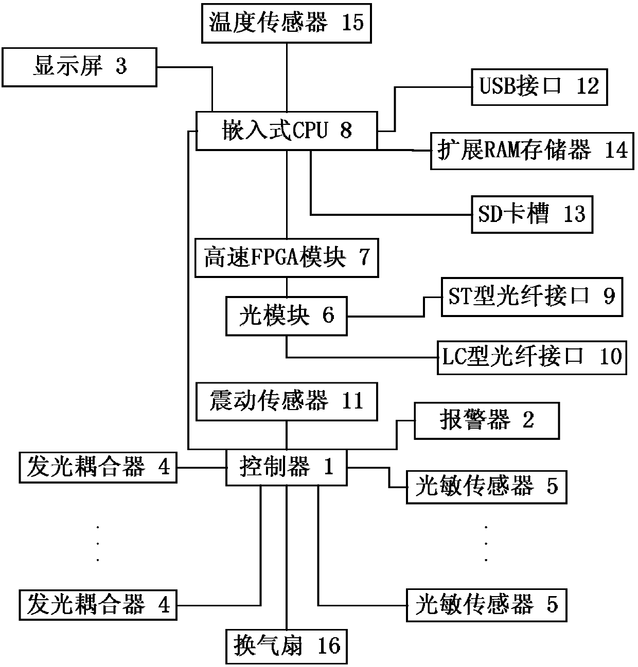
[0045] like figure 1 The illustrated embodiment is a fiber management box, including a controller 1, an alarm 2 and a housing. The other five shells of the body include an inner shell and an outer shell, and each inner shell and outer shell is provided with an optical fiber extending in a wave shape, and the corresponding optical fiber on the inner shell and outer shell The direction is perpendicular to each other, and also includes 10 light-emitting couplers 4 electrically connected to the optical input ends of each optical fiber and 10 photosensitive sensors 5 electrically connected to the optical output ends of each optical fiber; The device, the ventilation fan, each luminous coupler and each photosensitive sensor are electrically connected.

[0046] The housing is provided with an optical module 6, a high-speed FPGA module 7 and an embedded CPU 8 that are electrically connected in sequence. The housing is provided with an ST-type optical fiber interface 9 and an LC-type ...

Embodiment 2

[0056] Embodiment 2 includes all the structures and method parts of Embodiment 1, and Embodiment 2 also includes a shock sensor, and the shock sensor is electrically connected to the controller; it also includes the following steps:

[0057] The vibration sensor detects the vibration signal, and the vibration threshold is set in the controller. When the detected vibration value is higher than the vibration threshold, the controller controls the controller to alarm, and the staff performs manual intervention.


PUM

PropertyMeasurementUnit
Diameteraaaaaaaaaa
Diameteraaaaaaaaaa

Abstract

The invention discloses an optical fiber management box and a method. The optical fiber management box comprises a controller, an alarm and a shell, and is characterized in that the shell is rectangular, one shell plate of the shell is provided with a display screen, a temperature sensor and a ventilating fan, another five shell plates of the shell respectively comprise an inner shell plate and anouter shell plate, each inner shell plate and each outer shell plate are provided with optical fibers extending in a wave-shaped manner, and the optical fibers on the corresponding inner shell platesand outer shell plates are perpendicular to each other in trend, and the optical fiber management box further comprises 10 light-emitting couplers which are electrically connected with light input ends of the optical fibers and 10 photosensitive sensors which are electrically connected with light output ends of the optical fibers; and the controller is electrically connected with the temperaturesensor, the alarm, the ventilating fan, the light-emitting couplers and the photosensitive sensors. The optical fiber management box has the characteristics that the deformation and breakage of the shell can be timely detected and the alarm information can be timely sent out.

Description

technical field [0001] The technical field of optical fiber management equipment of the present invention, in particular, relates to a safe optical fiber management box and method. Background technique [0002] With the popularization of smart substation technology, optical fiber is widely used in substations. Compared with traditional cables, optical fiber transmission has the advantages of low loss, light weight, strong anti-interference ability, and convenient laying, which has brought another technological revolution to substation construction. But from the point of view of actual operation, the extensive use of optical fibers has brought some new challenges to routine maintenance. Due to the large number of optical fibers on the backplane of the protection device in the smart substation, if the optical fiber needs to be inserted and removed during the maintenance process, the maintenance personnel need to face problems such as too many secondary safety measures recorde...

Claims


Application Information

Patent Timeline
IPC IPC(8): G02B6/44
Inventor 陈全观田春华金建炜言伟黄龙飞周程肖陆明中王阳杨林严惟冰吴晓东
Owner STATE GRID ZHEJIANG ELECTRIC POWER CO LTD JIAXING POWER SUPPLY CO
Learn More