Motor rotor assembly

A motor rotor and rotor technology, applied in the direction of magnetic circuit rotating parts, magnetic circuit shape/style/structure, etc., can solve the problem that the shaft is separated from the rotor cylinder, which affects the normal use of the motor rotor assembly, and the shaft and the top of the rotor cylinder Problems such as breakage and cracking at the joint, to reduce the effect of breakage

Inactive Publication Date: 2019-03-08
GUIYANG AVIATION MOTOR
View PDF0 Cites 4 Cited by
  • Summary
  • Abstract
  • Description
  • Claims
  • Application Information

AI Technical Summary

Problems solved by technology

[0004] The purpose of the present invention is to provide a motor rotor assembly to solve the problem that the rotating shaft and the rotor cylinder are prone to detachment during long-term use of the motor rotor assembl

Method used


Image

  • Motor rotor assembly
  • Motor rotor assembly
  • Motor rotor assembly

Examples


Example Embodiment

[0019] The technical solutions in the embodiments of the present invention will be clearly and completely described below in conjunction with the accompanying drawings in the embodiments of the present invention. Obviously, the described embodiments are only a part of the embodiments of the present invention, rather than all the embodiments. Based on the embodiments of the present invention, all other embodiments obtained by those of ordinary skill in the art without creative work shall fall within the protection scope of the present invention.

[0020] See Figure 1-5 , The present invention provides a technical solution:

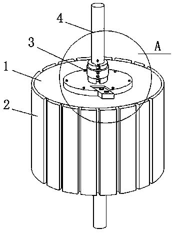
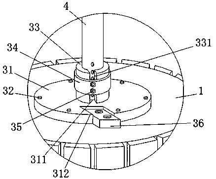
[0021] The motor rotor assembly includes a rotor cylinder 1, a rotor iron core connected to the outer side wall of the rotor cylinder 1 at intervals, a rotating shaft 4 vertically extending into the middle of the inner cavity of the rotor cylinder 1, and a mirror image arranged and fixedly connected to the rotor The connecting protection mechanism 3 at the end...


PUM


Abstract

The invention discloses a motor rotor assembly, comprising a rotor cylinder, rotor cores, a rotating shaft and a connection protecting mechanism; the rotor cores are spaced apart from the outer side wall of the rotor cylinder, the rotating shaft extends vertically into the middle portion of the inner cavity of the rotor cylinder, the connection protecting mechanism is mirror-arranged and fixedly connected to the end of the rotor cylinder, and the connection protecting mechanism is fixedly connected to a joint between the rotor cylinder and the rotating shaft. According to the motor rotor assembly, a reinforcing protection structure can be formed at the joint between the rotating shaft and the rotor cylinder, so that the rotating shaft and the rotor cylinder are always firmly integrated, thereby preventing the rotating shaft from being separated from the rotor cylinder during use to affect the normal use of the motor rotor assembly, and simultaneously enclosure protection is carried outon the joint between the rotating shaft and the rotor cylinder, thereby reducing the probability of breakage and fracture at the joint between the rotating shaft and the top of the rotor cylinder when the motor rotor assembly is in use.

Description

technical field [0001] The invention relates to the technical field of motors, in particular to a motor rotor assembly. Background technique [0002] The motor refers to an electromagnetic device that realizes the conversion or transmission of electric energy according to the law of electromagnetic induction. The rotor assembly is a part of the motor. With the continuous development of science and technology, different types of motor rotor assemblies have appeared in the market. The motor rotor assembly includes rotor columns. Body, rotor core and shaft. [0003] However, in the current motor rotor assembly on the market, when the motor rotor assembly is used for a long time, it is prone to the problem that the shaft and the rotor cylinder are separated, causing the problem of breaking and cracking at the connection between the shaft and the top of the rotor cylinder, which affects the normal operation of the motor rotor assembly. Use, is unfavorable for popularizing and us...

Claims


Application Information

Patent Timeline
IPC IPC(8): H02K1/28
CPCH02K1/28
Inventor 袁光伟
Owner GUIYANG AVIATION MOTOR
Why Eureka
Try Eureka