Supercharge Your Innovation With Domain-Expert AI Agents!

A power supply topology and control method for high-speed railway system over-phase separation

A topology, high-speed railway technology, applied in power lines, circuit devices, electrical components, etc., can solve problems such as unbalance, restrict safe and reliable operation, and exceed standards.

Active Publication Date: 2021-09-14
WUHAN UNIV
View PDF0 Cites 2 Cited by
  • Summary
  • Abstract
  • Description
  • Claims
  • Application Information

AI Technical Summary

Problems solved by technology

The problem of electric phase separation and automatic over-phase separation has been seriously restricting the safe and reliable operation of high-speed and heavy-duty trains. In order to eliminate the problems of overvoltage and over-current during the process of over-phase separation, it is necessary to install a complex automatic over-phase separation device
Although this scheme can realize the uninterrupted power splitting of the locomotive, the disadvantage is that the scheme requires that the locomotive must be deloaded to a idling state before entering the neutral section. Therefore, although the locomotive is always charged when passing through the electric split phase, the tractive force and speed are still limited. Loss; Tian Xu of Tsinghua University and others proposed a two-phase MMC uninterruptible power-over-phase-splitting device. Although the scheme uses frequency conversion phase-shifting technology, it can realize the locomotive without power failure and full power through electric phase-splitting, but due to its single-phase current On the one hand, the traction transformer on one side may be overloaded due to insufficient capacity, on the other hand, the load sequence imbalance may be aggravated and the unbalance degree may exceed the standard, resulting in application limitations

Method used


Image

  • A power supply topology and control method for high-speed railway system over-phase separation
  • A power supply topology and control method for high-speed railway system over-phase separation

Examples


Embodiment Construction

[0016] Embodiments of the present invention will be described in detail below in conjunction with the accompanying drawings.

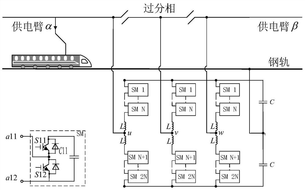
[0017] This embodiment is realized through the following technical solutions, as figure 1 As shown, a power supply topology for high-speed railway system with over-phase separation is u, v, w three-phase multi-level converter module branch, and each phase multi-level converter module branch is divided into upper bridge arm and the lower bridge arm, the upper bridge arm and the lower bridge arm of the u, v, w three-phase multi-level converter module branches are respectively composed of n multi-level converter modules MMC and a buffer inductor, The bridge arm and the lower bridge arm are respectively composed of n capacitor modules, and n is a positive integer greater than 1; wherein, the second interface a12 of the first multilevel converter module MMC1 is connected to the second interface a12 of the second multilevel converter module MMC2 The n multi...


PUM


Abstract

The invention belongs to power electronics technology, and in particular relates to a power supply topology structure and a control method for over-phase separation of a high-speed railway system. The over-phase power supply topology includes u, v, w three-phase multi-level converter module branch and capacitor branch, and the u, v, w three-phase multi-level converter module branch is connected in parallel with the capacitor branch parallel connection; wherein, each phase multilevel converter module branch is divided into an upper bridge arm and a lower bridge arm, and the upper bridge arm and the lower bridge arm of each phase multilevel converter module branch include sequentially connected in series n multilevel converter modules and buffer inductors connected in series, n is a positive integer greater than 1; the capacitor branch is divided into the upper bridge arm and the lower bridge arm on the DC bus side, and the upper bridge arm and the lower bridge arm on the DC bus side Each bridge arm includes n capacitor modules connected in series in sequence. The over-phase split power supply topology can take current in both directions according to the actual situation of the traction network on both sides, so that the train can pass through the over-split phase without continuous power supply, and has the advantage of not needing a transformer to be connected.

Description

technical field [0001] The invention belongs to the technical field of power electronics, and in particular relates to a power supply topology and a control method for over-phase separation of a high-speed railway system. Background technique [0002] In my country's current power grid model, when there is a higher-level power grid, the lower-level power grid is often no longer operated in a loop. Therefore, when 110kV or 220kV is used to supply power to the traction transformer, unilateral power supply or radial power supply is often used. . When using this power supply method, the voltage difference between adjacent power supply arms is very large, and the power supply arms of different voltage phases cannot be directly connected, so there is an isolation section between the two-phase power supply arms, which needs to pass through the isolation link every 20-30km For electrical isolation, it is generally called an electrical phase separation area in the traction power supp...

Claims


Application Information

Patent Timeline
Patent Type & Authority Patents(China)
IPC IPC(8): B60M3/00H02J3/00
CPCB60M3/00H02J3/005
Inventor 袁佳歆肖非然倪周
Owner WUHAN UNIV
Features
  • R&D
  • Intellectual Property
  • Life Sciences
  • Materials
  • Tech Scout
  • Unparalleled Data Quality
  • Higher Quality Content
  • 60% Fewer Hallucinations
Learn More