Terminal cutting device

A cutting and terminal technology, which is applied in contact manufacturing, metal processing, etc., can solve the problems of low production efficiency of terminal cutting and reduce feeding tact, and achieve the effect of reducing the feeding tact and improving production efficiency

Pending Publication Date: 2019-03-22
天泽精密技术(上海)有限公司
View PDF0 Cites 3 Cited by
  • Summary
  • Abstract
  • Description
  • Claims
  • Application Information

AI Technical Summary

Problems solved by technology

[0003] The purpose of the present invention is to provide a terminal cutting device in order to overcome the problem of low production efficiency of terminal cutting in the prior art. The structure pushes the feeding rail to slide on the slider seat. After the feeding is in place, the pushing structure can pull the feeding rail back to the original point for the next feeding. This design greatly reduces the feeding beat and improves the terminal cutting. cutting productivity

Method used


Image

  • Terminal cutting device
  • Terminal cutting device
  • Terminal cutting device

Examples


Embodiment Construction

[0060] Specific embodiments of the present invention will be described in detail below in conjunction with the accompanying drawings. It should be understood that the specific embodiments described here are only used to illustrate and explain the present invention, not to limit the present invention.

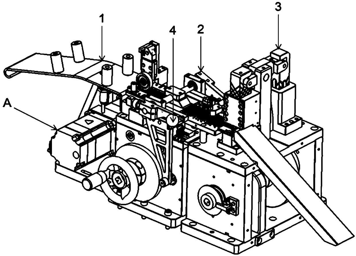
[0061] figure 1 A schematic structural view of a terminal cutting device provided according to an embodiment of the present invention is shown. Embodiments of the present invention provide a terminal cutting device, such as figure 1 As shown, the terminal cutting device may include a feeding channel 1 , a feeding mechanism 2 and a cutting mechanism 3 . The terminal strip enters the feeding mechanism 2 from the feeding channel 1 of the terminal cutting device, and the feeding mechanism 2 sends the terminal strip to the cutting mechanism 3 for cutting to obtain terminal products meeting requirements.

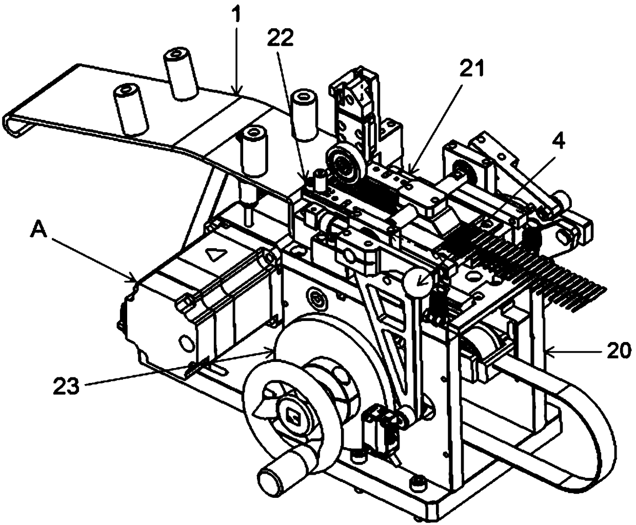
[0062] figure 2 A schematic diagram of a feeding mechanism of a terminal c...


PUM


Abstract

The invention relates to the field of terminal production, and discloses a terminal cutting device. The terminal cutting device comprises a feeding way, a conveying mechanism and a cutting mechanism;and the conveying mechanism comprises a main body, a sliding block seat, a conveying rail and a pushing structure, wherein the sliding block seat is arranged on the main body, the conveying rail is slidably arranged on the sliding block seat, and the pushing structure is used for pushing the conveying rail to slide on the sliding block seat. The terminal cutting device comprises the conveying railarranged on the sliding block seat, the conveying rail is pushed through the pushing structure to slide on the sliding block seat, a first pressure spring is connected between the conveying rail andthe sliding block seat, after conveying is conducted in place, the pushing structure can pull the conveying rail back to the original point to conduct conveying of the next time, through the design, the takt time of conveying is slowed greatly, and thus the production efficiency of terminal cutting is improved.

Description

technical field [0001] The invention relates to the field of terminal production, in particular to a terminal cutting device. Background technique [0002] Electronic components, especially various connectors, usually include many metal PIN pins, also called terminals. The above-mentioned terminals are fixed on the plastic base by means of injection molding or pressing to form a connecting piece. When the terminal product leaves the factory, it is usually fixed on the strip, and many PIN needles are arranged on a long metal strip to form a very long strip roll. In the prior art, the cutting mechanism usually uses a fixing mechanism with positioning pins to fix the material tape, and then drives the material tape forward for cutting. The feeding cycle is slow, resulting in low production efficiency of terminal cutting. Contents of the invention [0003] The purpose of the present invention is to provide a terminal cutting device in order to overcome the problem of low pro...

Claims


Application Information

Patent Timeline
Patent Type & Authority Applications(China)
IPC IPC(8): B26D1/08B26D7/06B26D5/16H01R43/16
CPCB26D1/08B26D5/16B26D7/0608B26D7/0683H01R43/16
Inventor 黄明刘超邵玉杰
Owner 天泽精密技术(上海)有限公司
Why Eureka
Try Eureka