Automatic ejection device for injection molds

An automatic ejection and injection mold technology, applied in the field of injection molds, can solve problems such as complex results, additional air sources, and low strength

Inactive Publication Date: 2019-03-22
嘉兴市六和塑料制品有限公司
View PDF0 Cites 1 Cited by
  • Summary
  • Abstract
  • Description
  • Claims
  • Application Information

AI Technical Summary

Problems solved by technology

Although the hydraulic ejection device is convenient to adjust the speed, position and stroke, the result is complicated and the force is small
Although the method of using compressed air to blow out plastic products between air pressures will not leave marks on the plastic products, it is necessary to set air passages and air holes on the mold, and it is necessary to add an air source

Method used


Image

  • Automatic ejection device for injection molds
  • Automatic ejection device for injection molds

Examples


Embodiment Construction

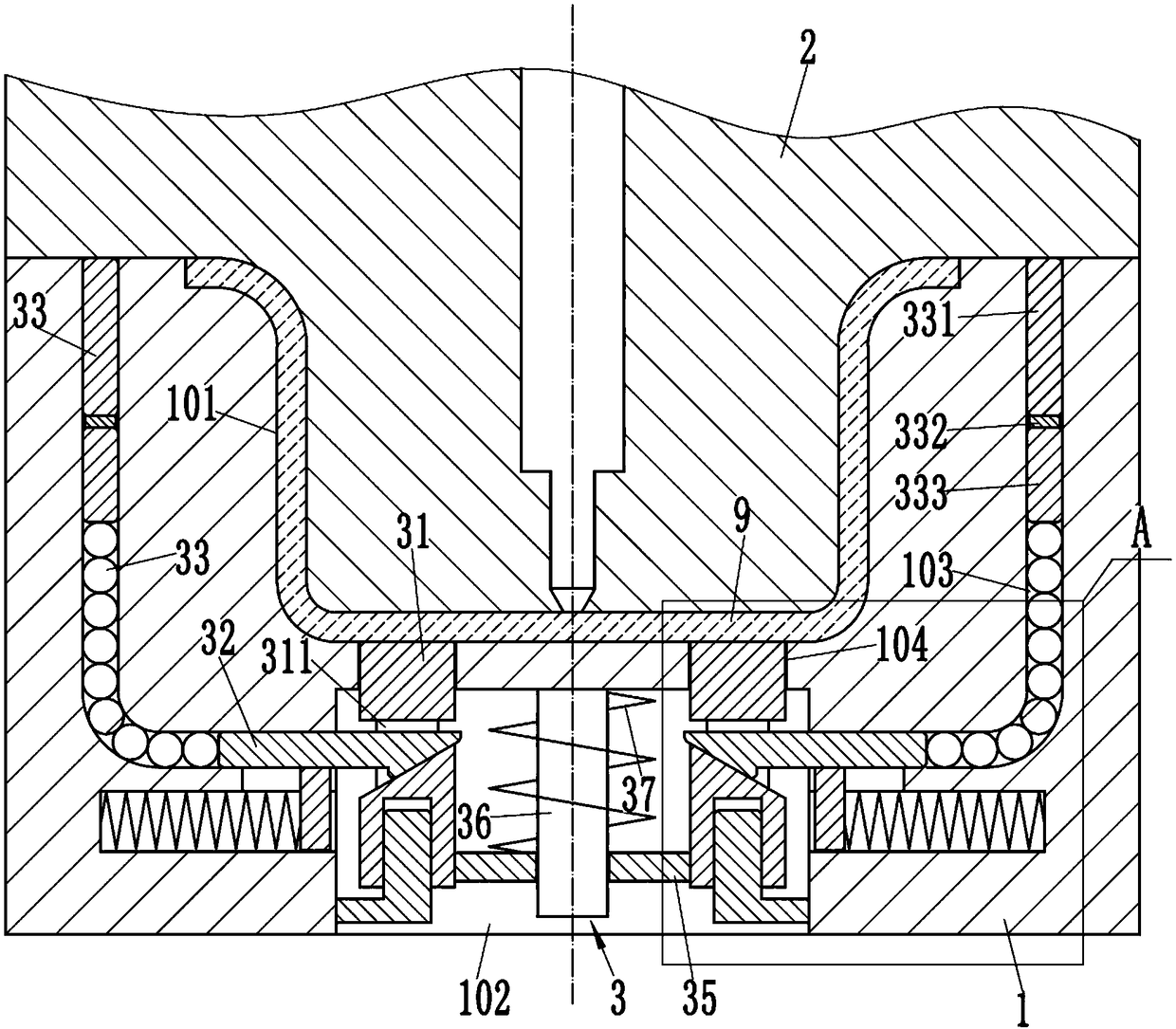
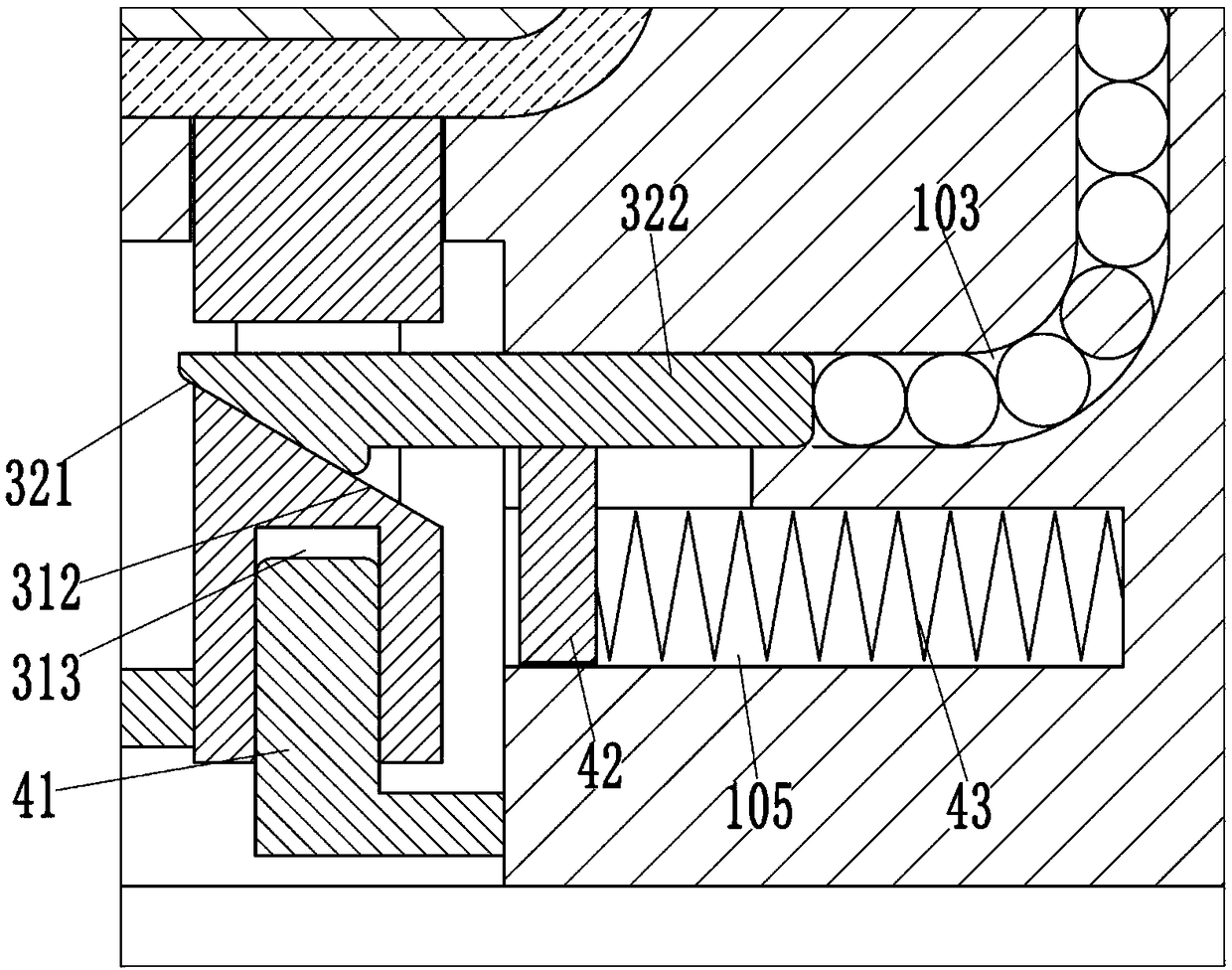
[0014] Example, see as Figure 1 to Figure 2 As shown, an automatic ejection device for an injection mold includes a concave mold 1 and a convex mold 2 that can move up and down. The concave mold 1 is formed with a concave mold cavity 101, and the convex part of the convex mold 2 is inserted into the concave mold cavity 101 , The plastic product 9 is molded in the cavity formed by the concave mold cavity 101 and the convex mold 2. The concave mold 1 is provided with an automatic ejection device 3, and the concave mold 1 is molded with a driving cavity 102 with a lower side opening and a For the L-shaped channel 103 arranged symmetrically, the lower end of the L-shaped channel 103 communicates with the driving cavity 102. Two parallel thimble holes 104 are provided between the cavity 101 and the driving cavity 102. The outlet device 3 includes two thimble pins 31 respectively inserted and sleeved in the two thimble holes 104. The center of the thimble 31 is formed with a left an...


PUM


Abstract

The invention discloses an automatic ejection device for injection molds. The automatic ejection device comprises a female mold and a male mold. A female mold cavity is formed in the female mold. An automatic ejection device body is arranged in the female mold. A drive cavity and a pair of L-shaped channels are formed in the female mold. Two ejector pin holes are formed between the female mold cavity and the drive cavity. The automatic ejection device body comprises two ejector pins which are inserted into the two ejector holes in a sleeved manner correspondingly. An opening is formed in the middle portion of each ejector pin. A drive block is sleeved with each opening. Each drive block comprises a first slope and an inserting rod. Each first slope presses against a second slope of the corresponding opening. Each inserting rod is inserted into a transverse channel of one corresponding L-shaped channel. Pressing rods are sleeved with vertical channels of the L-shaped channels. The upperends of the pressing rods press against the male mold. A plurality of steel balls are arranged between the pressing rods and the inserting rods. The lower ends of the two ejector pins are fixedly connected through a lifting plate. The lifting plate is arranged on a core shaft in a sleeving manner. The core shaft is sleeved with a pulling spring. According to the automatic ejection device, under the circumstance of not needing independent drive power, plastic products can be ejected automatically.

Description

Technical field: [0001] The invention relates to the technical field of injection molds, in particular to an automatic ejection device for injection molds. Background technique: [0002] The opening and closing part of the injection molding machine of the ejector device is a device that realizes the ejection and drop function of plastic products in linkage with the mold. Commonly used ejector devices mostly have independent driving power, such as hydraulic or pneumatic. Although the hydraulic ejector is convenient to adjust the speed, position and stroke, the result is complicated and the force is small. Although the method of blowing out plastic products between compressed air pressure will not leave marks on the plastic products, it is necessary to provide air passages and pores on the mold, and an additional air source is required. Summary of the invention: [0003] The purpose of the present invention is to overcome the shortcomings of the prior art and provide an automatic ...

Claims


Application Information

Patent Timeline
Patent Type & Authority Applications(China)
IPC IPC(8): B29C45/40
CPCB29C45/4005
Inventor 翁国峰
Owner 嘉兴市六和塑料制品有限公司
Why Eureka
Try Eureka