Lamp mounting device with reverse conducting structure

A lamp installation and reverse conduction technology, which is applied to lighting devices, circuit layout, fixed lighting devices, etc., can solve problems such as troublesome installation, poor contact, and exposed conductive sheets or conductive joints of neutral and live wires, etc., to achieve Easy installation and disassembly, stable installation, excellent contact conductivity

Pending Publication Date: 2019-03-22
DONGGUAN TAIXIN LIGHTING
View PDF0 Cites 0 Cited by
  • Summary
  • Abstract
  • Description
  • Claims
  • Application Information

AI Technical Summary

Problems solved by technology

It has the following defects: first, installation is troublesome, wiring, chassis installation, lampshade installation, etc. need to be completed step by step, and the lamp body cannot be installed as a whole, it is necessary to install the dial first and then install the lamp body; second, the lamp body After installation, the stability is relatively poor; third, after the installation of the lamp, the contact between the neutral wire and the live wire is not close enough, and the problem of poor contact is prone to occur; fourth, the biggest problem in the prior art is the conductive connection between the neutral wire and the live wire. The strips or conductive joints are exposed to the outside. When workers install the lamps, they are easy to touch the conductive strips or conductive joints of the neutral line and the live line, which is low in safety.

Method used


Image

  • Lamp mounting device with reverse conducting structure
  • Lamp mounting device with reverse conducting structure
  • Lamp mounting device with reverse conducting structure

Examples


Embodiment Construction

[0027] In order to facilitate the understanding of the present invention, the present invention will be described more fully below with reference to the associated drawings. Preferred embodiments of the invention are shown in the accompanying drawings. However, the present invention can be embodied in many different forms and is not limited to the embodiments described herein. On the contrary, the purpose of providing these embodiments is to make the disclosure of the present invention more thorough and comprehensive. The directional terms such as "upper end" and "lower end" herein are only based on the accompanying drawings, in order to facilitate the description of the application and simplify the description, and do not indicate or imply that the device or element referred to must have a specific orientation or be constructed in a specific orientation. and operation, and therefore cannot be construed as limiting the application.

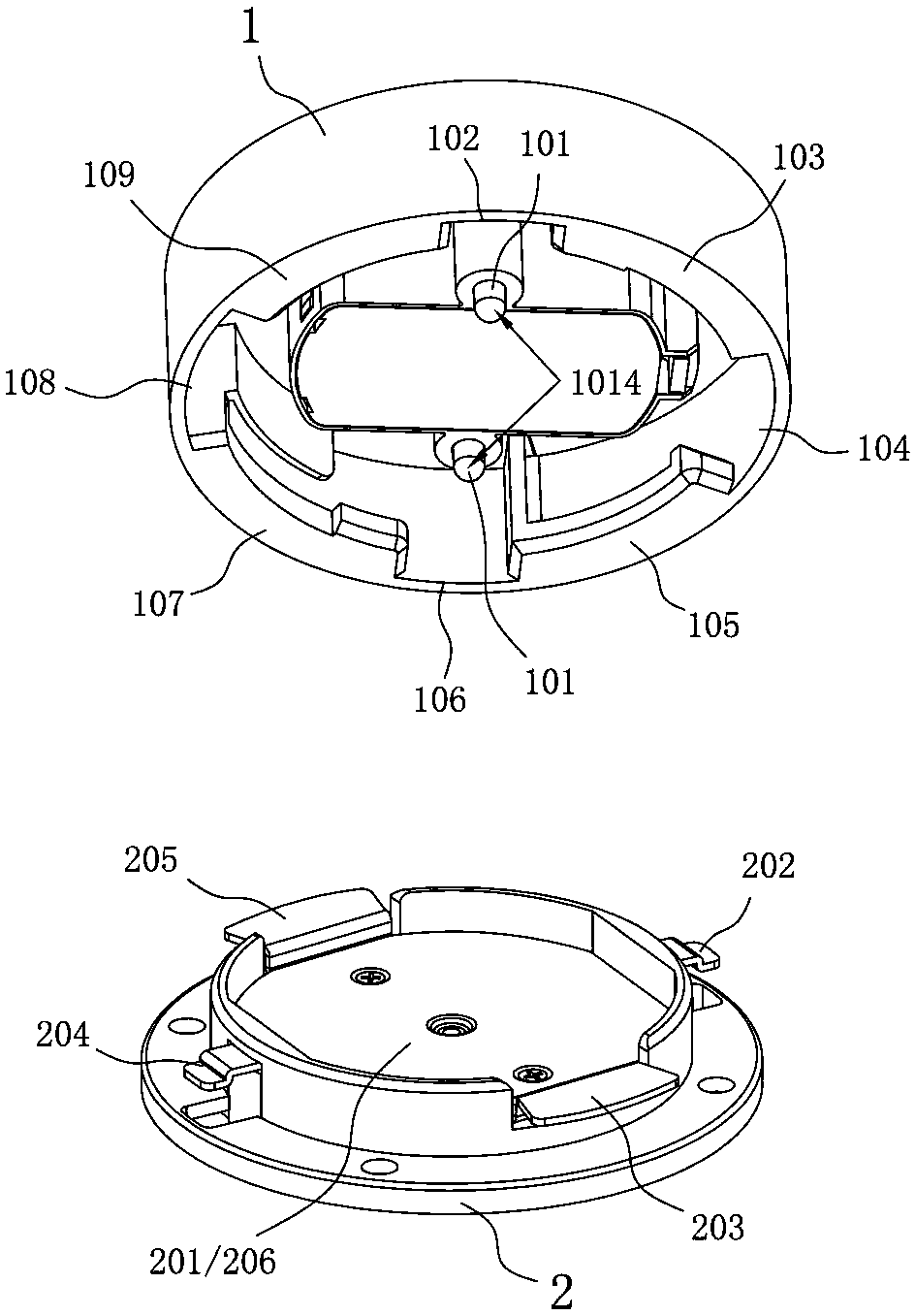
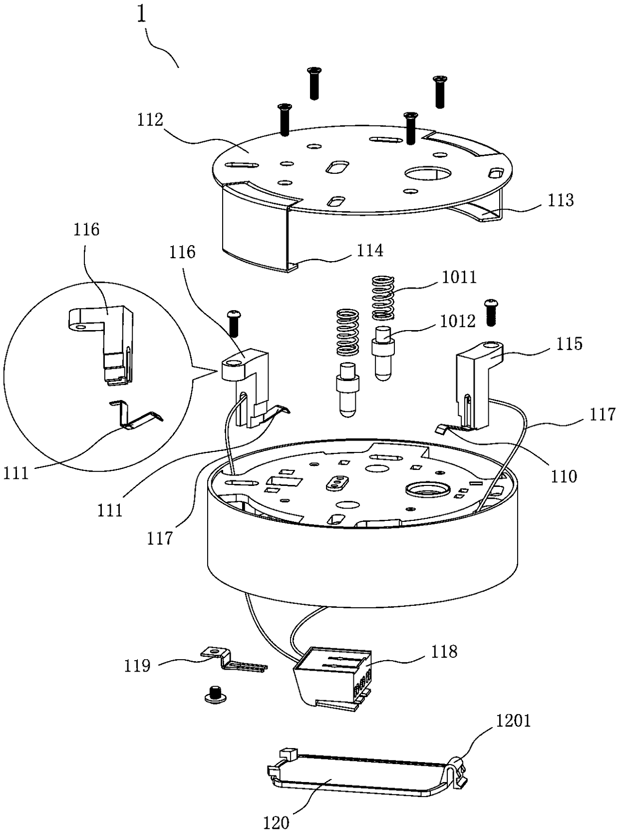
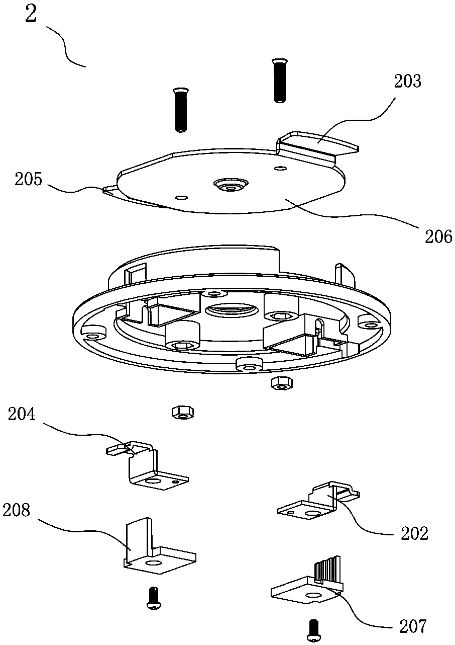
[0028] Such as Figure 1-Figure 10 As sh...


PUM


Abstract

The invention discloses a lamp mounting device with a reverse conducting structure. The lamp mounting device comprises a first conducting box and a second conducting box; an elastic grounding assemblyis arranged in the first conducting box, and a first conducting piece guiding opening, a first conducting piece partition wall, a first fixing piece guiding opening, a first fixing piece partition wall, a second conducting piece guiding opening, a second conducting piece partition wall, a second fixing piece guiding opening and a second fixing piece partition wall are sequentially arranged in thecircumferential direction of the lower end of the first conducting box; a first conducting piece is mounted in the first conducting piece partition wall, and a second conducting piece is mounted in the second conducting piece partition wall; and a grounding metal surface is arranged on the upper side of the second conducting box, and a first bent conducting piece, a first fixing piece, a second bent conducting piece and a second fixing piece are sequentially arranged in the circumferential direction of the upper end of the second conducting box. The lamp mounting device can be quickly and conveniently mounted or demounted, and is good in stability and excellent in contacting of the conducting pieces, the conducting pieces are hidden in the conducting piece partition walls and thus are notprone to being touched, and safety is high.

Description

technical field [0001] The invention relates to the field of lamps, in particular to a lamp installation device with a reverse conductive structure. Background technique [0002] At present, when the lamp and the lamp holder are installed, the lamp is connected with the lamp or the chassis is installed, then the wiring is performed, and then the lampshade is installed. It has the following defects: first, installation is troublesome, wiring, chassis installation, lampshade installation, etc. need to be completed step by step, and the lamp body cannot be installed as a whole, it is necessary to install the dial first and then install the lamp body; second, the lamp body After installation, the stability is relatively poor; third, after the installation of the light fixture, the contact between the neutral wire and the live wire is not close enough, and the problem of poor contact is prone to occur; fourth, the biggest problem in the prior art is the conductive connection betw...

Claims


Application Information

Patent Timeline
Patent Type & Authority Applications(China)
IPC IPC(8): F21S8/04F21V17/12F21V17/16F21V23/06F21V25/00
CPCF21S8/04F21V17/12F21V17/162F21V23/06F21V25/00
Inventor 时光韩欧
Owner DONGGUAN TAIXIN LIGHTING
Why Eureka
Try Eureka