
Method and apparatus for decoding two-dimensional code

A decoding method and two-dimensional code technology, applied in electromagnetic radiation induction, instruments, induction record carriers, etc., can solve problems such as failure, inability to apply QR code version, etc., to achieve the effect of improving reading performance

Active Publication Date: 2019-03-22
SHANGHAI SUMI TECH CO LTD
View PDF6 Cites 6 Cited by
  • Summary
  • Abstract
  • Description
  • Claims
  • Application Information

AI Technical Summary

Problems solved by technology

Therefore, the method of CN 104463059A, which relies on the correction graphics in the lower right corner, cannot be applied to all QR code versions
The method of CN105138943B relies more on the boundary line of the position detection figure. Once the size of the position detection figure is small or it is difficult to fit a more accurate straight line (for example, some position detection figures are designed as circles), the method becomes invalid

Method used


Image

  • Method and apparatus for decoding two-dimensional code
  • Method and apparatus for decoding two-dimensional code
  • Method and apparatus for decoding two-dimensional code

Examples


Embodiment 1

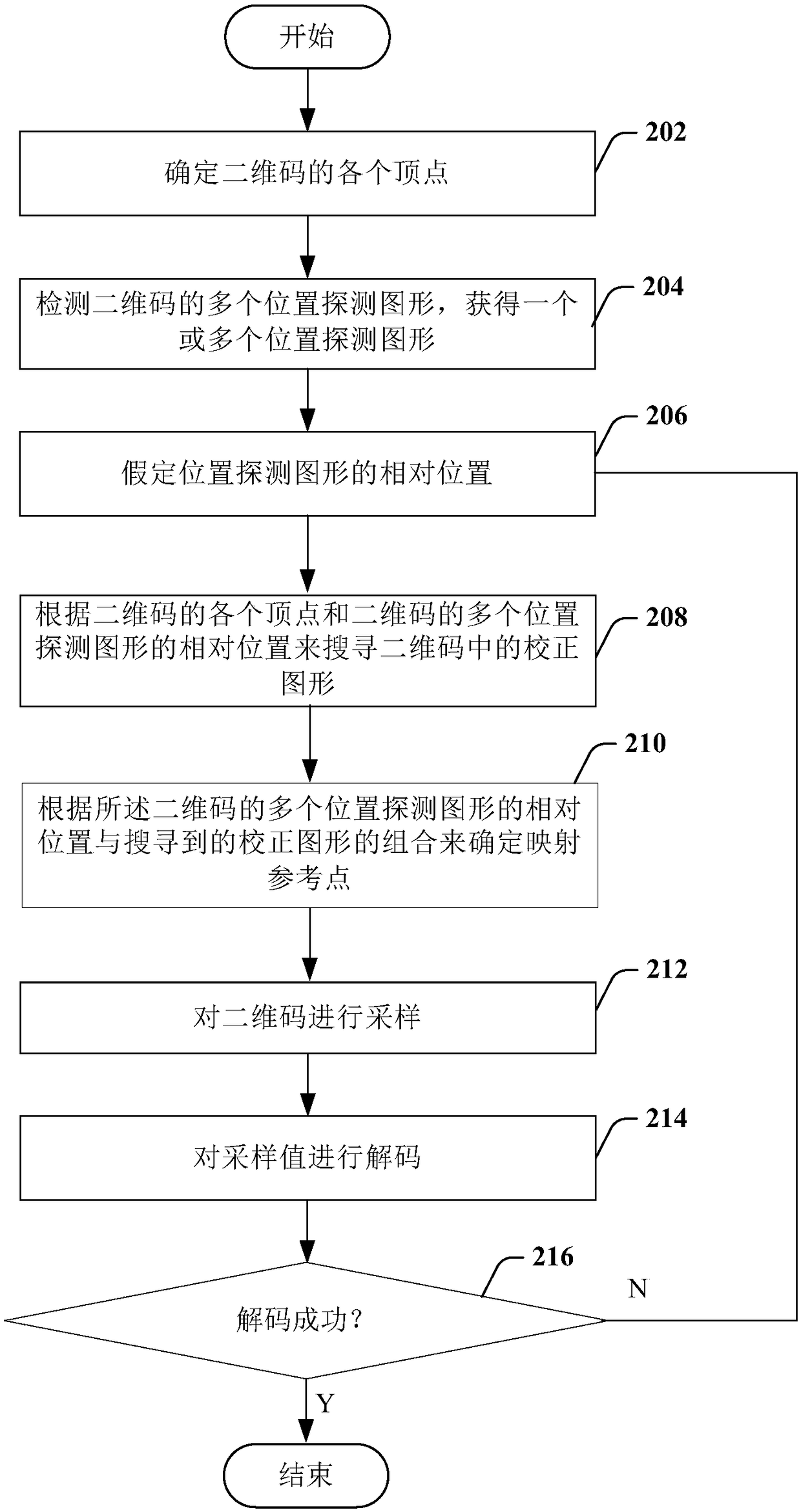
[0036] figure 2 It is a flowchart of a decoding method for determining a two-dimensional code according to an embodiment of the present invention. refer to figure 2 As shown, a decoding method for determining a two-dimensional code in this embodiment may include the following steps.

[0037] In step 202, each vertex of the two-dimensional code is determined.

[0038]In this step, the 4 vertices of the QR code can be determined. There are many ways to obtain the 4 vertices of the QR code. For example, you can first obtain the 4 sides of the QR code, and then use the 4 sides to obtain 4 vertices.

[0039] If the boundary of the two-dimensional code image is greatly disturbed, it will affect the positioning of the outer boundary of the two-dimensional code and cause recognition failure. At this time, the four vertices on the periphery of the two-dimensional code can be obtained through other methods of processing, and no examples are given here.

[0040] In step 204, multi...

Embodiment 2

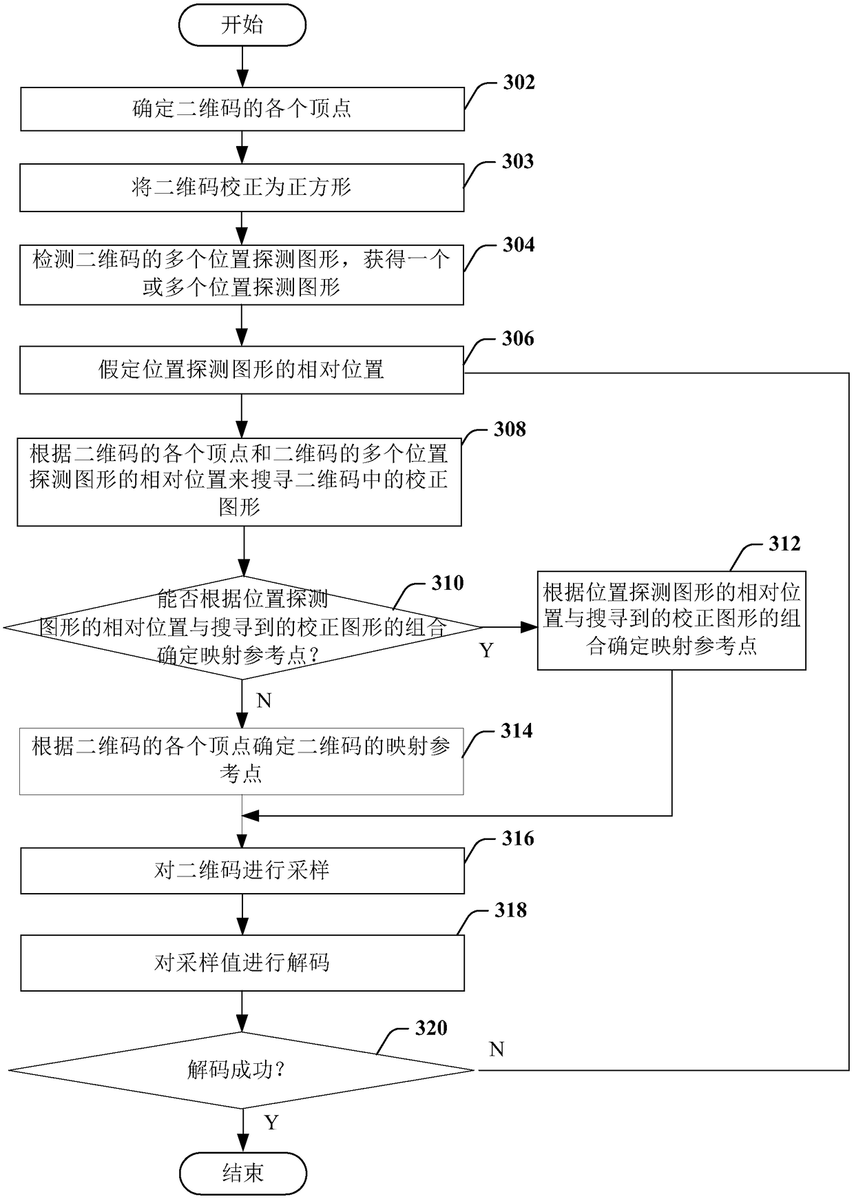
[0069] image 3 It is a flowchart of a decoding method for determining a two-dimensional code according to another embodiment of the present invention. refer to image 3 As shown, a decoding method for determining a two-dimensional code in this embodiment may include the following steps.

[0070] In step 302, each vertex of the two-dimensional code is determined.

[0071] In this step, the 4 vertices of the QR code can be determined. There are many ways to obtain the 4 vertices of the QR code. For example, you can first obtain the 4 sides of the QR code, and then use the 4 sides to obtain 4 vertices.

[0072] If the boundary of the two-dimensional code image is greatly disturbed, it will affect the positioning of the outer boundary of the two-dimensional code and cause recognition failure. At this time, the four vertices on the periphery of the two-dimensional code can be obtained through other methods of processing, and no examples are given here.

[0073] In step 303, t...


PUM


Abstract

The invention provides a Method for decoding two-dimensional code, comprising the following steps: a. Determining each vertex of the two-dimensional code; B. Detecting a plurality of position detection patterns of the two-dimensional code to obtain one or more position detection patterns; C. Assuming the relative positions of the plurality of position detection patterns of the two-dimensional codewhen the number of the one or more position detection patterns is less than a threshold sufficient to determine the relative positions of the plurality of position detection patterns of the two-dimensional code; D. Searching for a correction pattern in the two-dimensional code according to relative positions of respective vertices of the two-dimensional code and a plurality of position detectionpatterns of the two-dimensional code; E. Determining a mapping reference point based on a combination of a relative position of a plurality of position detection patterns of the two-dimensional code and a searched correction pattern; F. Sampling the two-dimensional code according to the mapping reference point; And g. Decoding the sampled value and returning to the step c to re-assume the relativepositions of the plurality of position detection patterns of the two-dimensional code when the decoding is unsuccessful.

Description

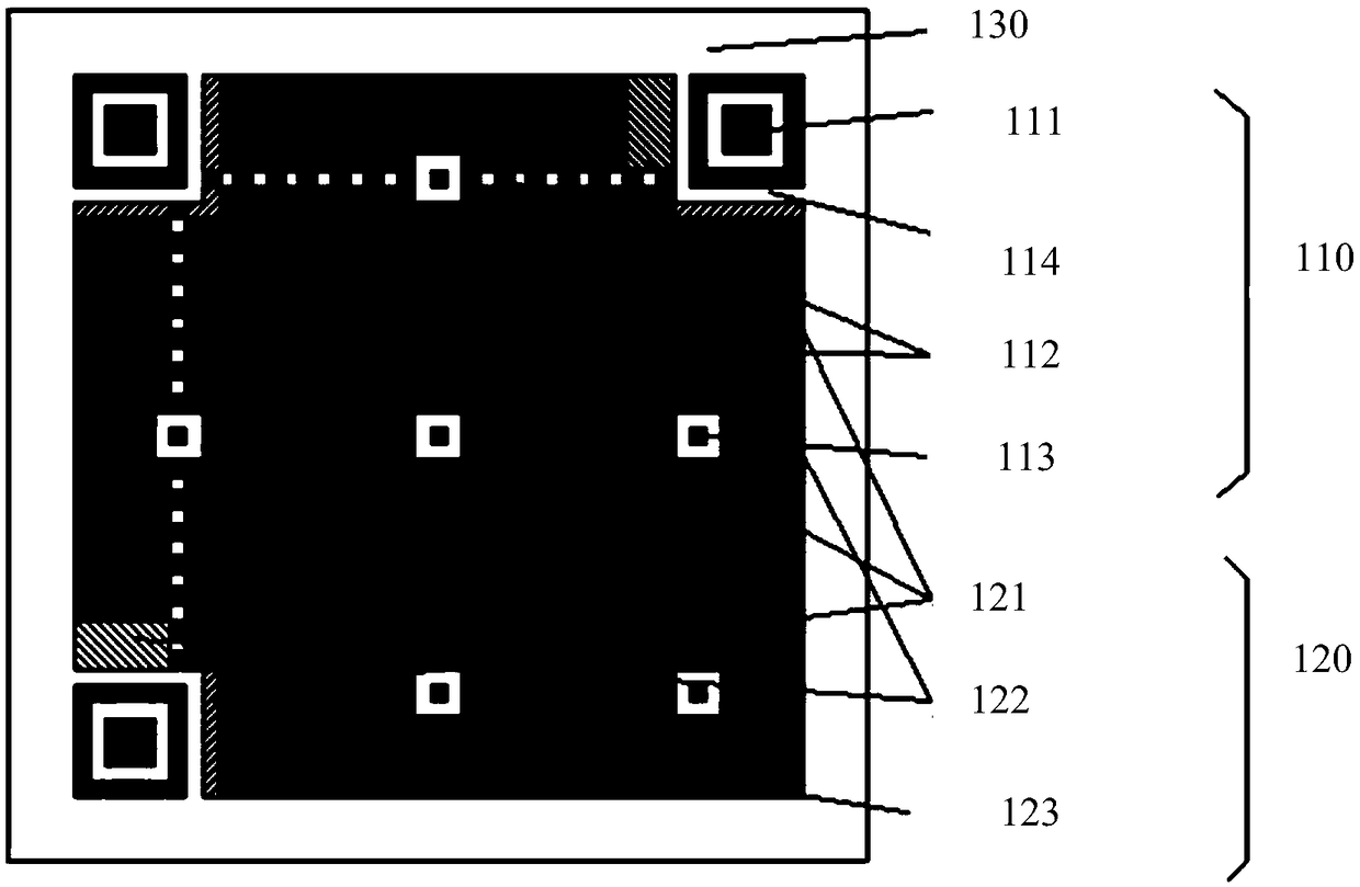
technical field [0001] The present invention mainly relates to the identification of two-dimensional codes, in particular to a method and device for determining the decoding of two-dimensional codes during the identification process of two-dimensional codes. Background technique [0002] QR (Quick Response, quick response) code is a typical two-dimensional code, which has been widely used in different industries with the development of mobile payment and the Internet of Things. figure 1 It is a schematic diagram of the composition structure of a QR code. Such as figure 1 As shown, the composition structure of the QR code includes a functional graphic area 110 , a coding area 120 and a blank area 130 . The functional graphic area 110 is mainly used to detect and locate barcodes and determine the positions of internal modules. The functional graphic area 110 includes a position detection graphic 111 , a positioning graphic 112 and a calibration graphic 113 . The position d...

Claims


Application Information

Patent Timeline
Patent Type & Authority Applications(China)
IPC IPC(8): G06K7/14
CPCG06K7/1417G06K7/1443G06K7/1452
Inventor 胡华侨
Owner SHANGHAI SUMI TECH CO LTD
Learn More