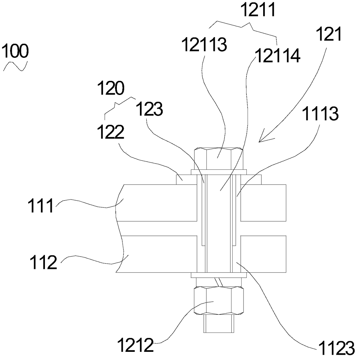
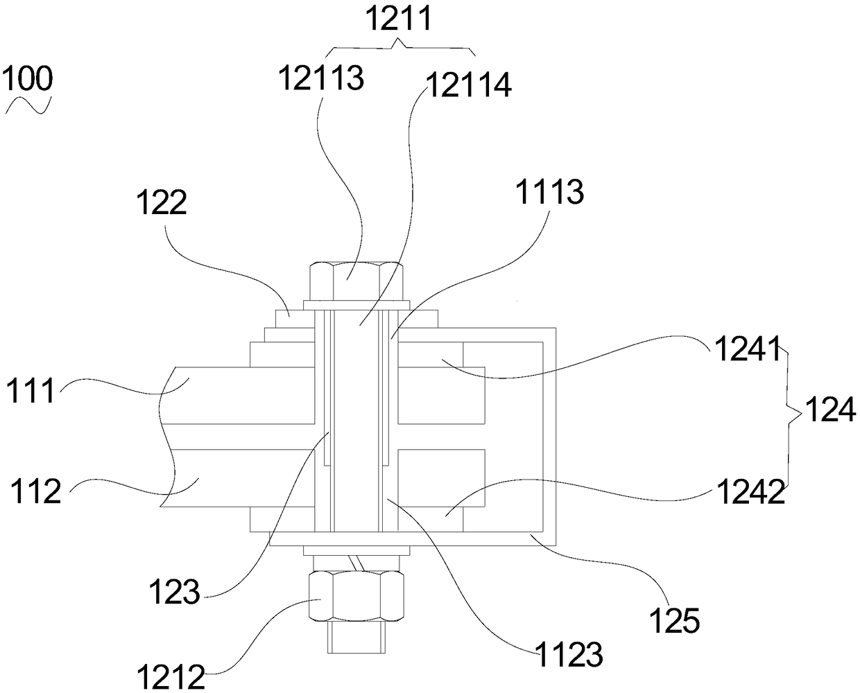
Box edge structure

A box edge and box body technology, applied in the field of transformers, can solve problems such as difficulty in operation

Pending Publication Date: 2019-03-22
特变电工湖南工程有限公司
View PDF0 Cites 0 Cited by
  • Summary
  • Abstract
  • Description
  • Claims
  • Application Information

AI Technical Summary

Problems solved by technology

[0004] Based on this, it is necessary to provide a box edge structure with simple operation for the problem that the traditional overheating prevention method is difficult to operate

Method used


Image

  • Box edge structure
  • Box edge structure

Examples


Embodiment Construction

[0020] In order to facilitate the understanding of the present invention, the second aspect will describe the present invention more fully with reference to the relevant drawings. Preferred embodiments of the invention are shown in the accompanying drawings. However, the present invention can be embodied in many different forms and is not limited to the embodiments described herein. On the contrary, these embodiments are provided to make the understanding of the disclosure of the present invention more thorough and comprehensive.

[0021] It should be noted that when an element is referred to as being “fixed” to another element, it can be directly on the other element or there can also be an intervening element. When an element is referred to as being "connected to" another element, it can be directly connected to the other element or intervening elements may also be present. The terms "vertical," "horizontal," "left," "right," and similar expressions are used herein for pur...


PUM


Abstract

The invention provides a box edge structure for fastening a first box body and a second box body. A grounding device is disposed on the second box body. The box edge structure comprises a first box edge and a second box edge overlapped with the first box edge. A metal connecting member is fixedly connected with the first box edge and the second box edge so as to fasten the first box edge and the second box edge. An insulating member is clamped between the metal connecting member and the firs box edge to realize insulation of the metal connecting member with the first box edge and electric connection of the metal connecting member with the second box edge. The box edge structure has the great operation convenience.

Description

technical field [0001] The invention relates to the technical field of transformers, in particular to a box edge structure. Background technique [0002] In the technical field of transformers, the box body of the transformer includes a first box body and a second box body covered with the first box body, and the first box body and the second box body cover are respectively formed with overlapping first box bodies. Along and the second box along. The first box edge and the second box edge are fastened by a plurality of metal connectors. [0003] Since the transformer will generate induced current during operation, the insulation method is usually used to prevent the metal connecting parts from overheating. Moreover, in order to prevent the metal connection parts from generating a floating potential when they are insulated, each metal connection part is also grounded. However, this method leads to greater difficulty in operation. Contents of the invention [0004] Based...

Claims


Application Information

Patent Timeline
IPC IPC(8): H01F27/02H01F27/34
CPCH01F27/02H01F27/34
Inventor 陈松云苏钟焕阴祖强詹小彬李先巧沈统先郑盈盈曹妙洪志敏谢伟
Owner 特变电工湖南工程有限公司
Why Eureka
Try Eureka