
Aircraft wing trimming device

An aircraft and airfoil technology, applied in the field of aircraft trim design, can solve the problems of increasing the pilot's control burden and not having the follow-up compensation function

Active Publication Date: 2022-04-19
SHAANXI AIRCRAFT CORPORATION
View PDF0 Cites 0 Cited by
  • Summary
  • Abstract
  • Description
  • Claims
  • Application Information

AI Technical Summary

Problems solved by technology

The disadvantage of the current trim is that it does not have a follow-up compensation function, which increases the driver's manipulation burden

Method used


Image

  • Aircraft wing trimming device
  • Aircraft wing trimming device

Examples


Embodiment Construction

[0012] Below in conjunction with accompanying drawing and specific embodiment the present invention is described in further detail:

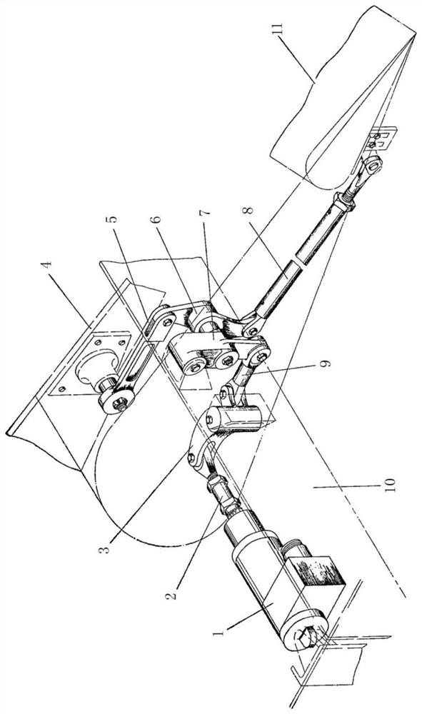
[0013] See attached figure 1 In this embodiment, an aircraft wing surface trimming device is proposed, including an electric mechanism 1, a first connecting rod 2, a first double-arm rocker 3, an aileron suspension arm 4, a second connecting rod 5, a second double Rocker arm 6, rocker arm 7, pull rod 8, third connecting rod 9, aileron beam 10 and aileron trim piece 11;

[0014] The electric mechanism 1 is installed on the aileron girder 10 , the actuator of the electric mechanism 1 is fixedly connected with one end of the first connecting rod 2 , and the other end of the first connecting rod 2 is connected with the first double-arm rocker arm 3 installed on the aileron girder 10 One support arm is hinged, the upper lug of the rocker arm 7 is hinged on the bracket of the aileron beam 10, the middle hole of the rocker arm 7 is hinged with the sec...


PUM


Abstract

The invention discloses an aircraft wing surface trimming device, which comprises an electric mechanism (1), a first connecting rod (2), a double-arm rocker (3), an aileron suspension arm (4), a second connecting rod (5 ), double-arm rocker arm (6), rocker arm (7), tie rod (8), third link (9), aileron beam (10) and aileron trim piece (11); when the aileron is deflected, Drive the aileron adjustment sheet (follow-up compensation sheet) to move the control mechanism to manipulate the aileron adjustment sheet (follow-up compensation sheet) to follow in the direction opposite to the aileron deflection direction. When the hydraulic source of the irreversible booster on one side of the aileron fails, set the "aileron adjustment / adjustment sheet" switch on the center console to the "adjustment sheet" position, and use the electric mechanism to deflect the aileron adjustment sheet to reduce the disk force. The beneficial effect of the invention is that it not only has the function of adjusting sheet, but also has the function of follow-up compensating sheet.

Description

technical field [0001] The invention relates to the field of aircraft trim design, in particular to an aircraft wing surface trim device. Background technique [0002] The trim tab control system is a control system independent of the main flight control. The deflection of the trim tab can reduce or offset the pilot's control force when manipulating the main control surface, and reduce the fatigue of long-term flight. The follow-up compensation plate does not need special manipulation by the driver, it is connected with the main control line system, and deflects in the opposite direction with the deflection of the main rudder / wing surface, reducing the pilot's control force. The disadvantage of the current trim is that it does not have a follow-up compensation function, which increases the driver's manipulation burden. Contents of the invention [0003] Purpose of the invention: the present invention overcomes the deficiencies in the prior art and provides an aircraft win...

Claims


Application Information

Patent Timeline
Patent Type & Authority Patents(China)
IPC IPC(8): B64F5/00B64F5/10
CPCB64F5/00B64F5/10
Inventor 杨涛徐坚宋娟妮石强军何松青吕明陈丰华车意彬何志国杨曦骆李平李晓茹朱永岗戴畅崔津铭
Owner SHAANXI AIRCRAFT CORPORATION
Learn More