
Full-automatic chamfering machine

A chamfering machine, fully automatic technology, applied in the direction of maintenance and safety accessories, metal processing machinery parts, metal processing, etc., can solve the problems of electric or pneumatic component erosion, affecting the service life of equipment, etc., to prevent powder erosion and facilitate Cleaning and maintenance, avoiding the effect of dust erosion

Active Publication Date: 2019-03-29
厦门瑞祺金属制品有限公司
View PDF7 Cites 0 Cited by
  • Summary
  • Abstract
  • Description
  • Claims
  • Application Information

AI Technical Summary

Problems solved by technology

[0004] The automatic chamfering work of the workpiece can be realized through the above-mentioned scheme. However, a large amount of powder chips will be generated when the inner chamfering processing of the pipe sleeve products is carried out. When sprayed on the chamfering machine, it is easy to cause corrosion to various electric or pneumatic components on the chamfering machine, which seriously affects the service life of the equipment

Method used


Image

  • Full-automatic chamfering machine
  • Full-automatic chamfering machine
  • Full-automatic chamfering machine

Examples


Embodiment Construction

[0041] The present invention will be described in detail below in conjunction with the accompanying drawings and embodiments.

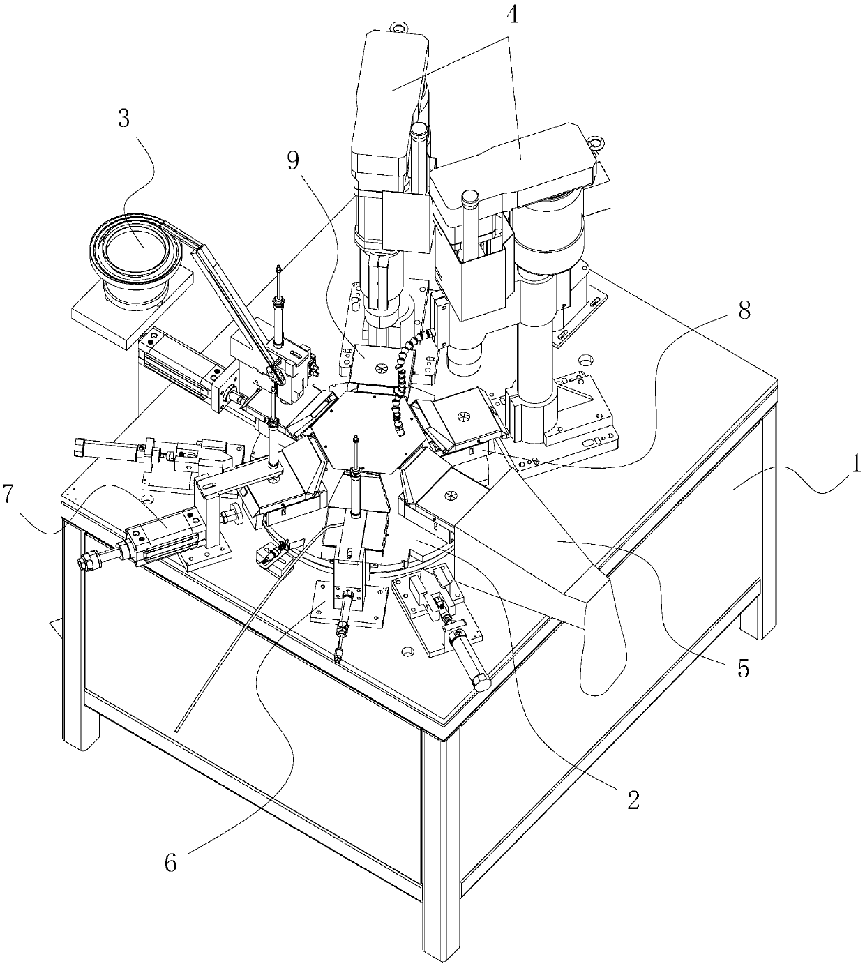
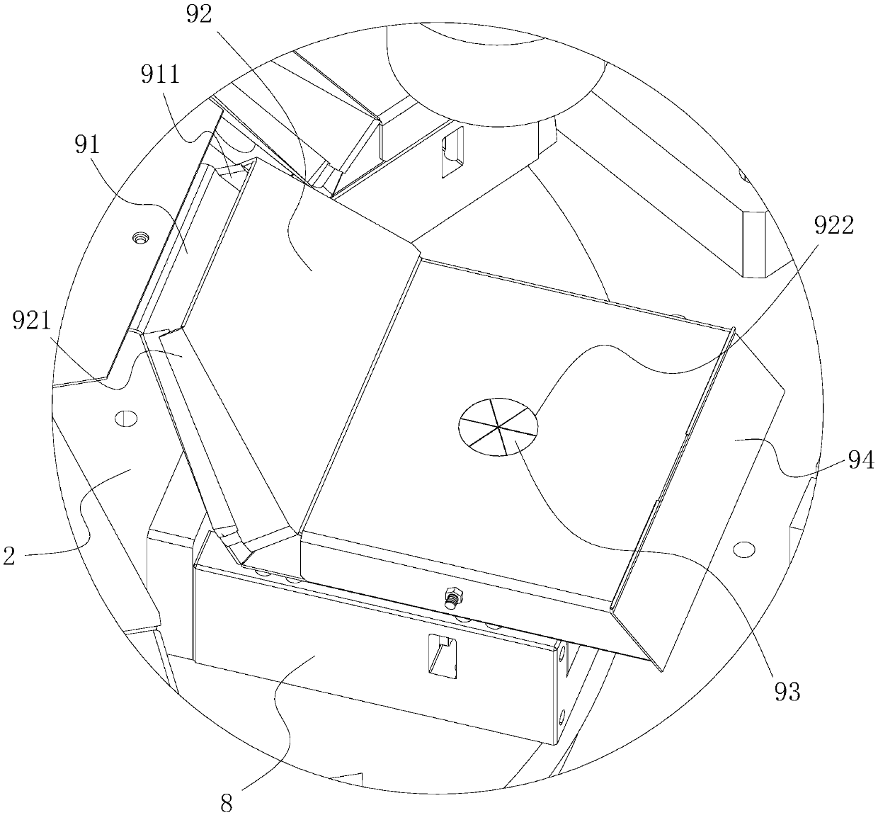
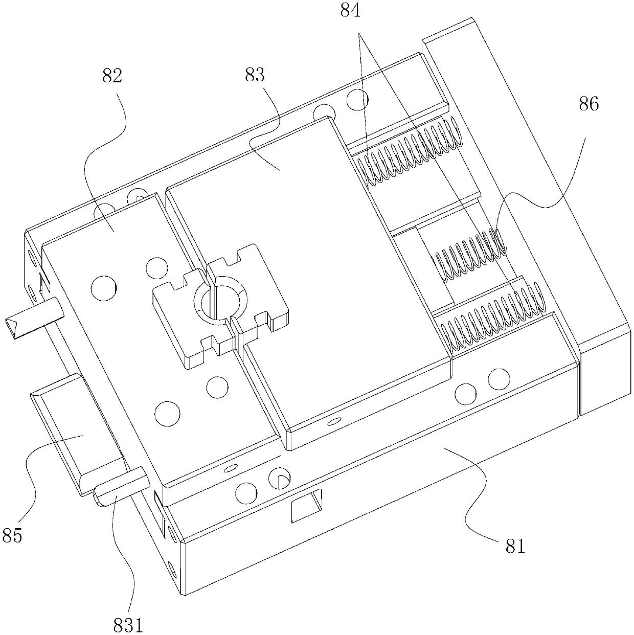
[0042] A fully automatic chamfering machine, such as figure 1 As shown, a frame 1 horizontally arranged on the ground, a turntable 2 rotatably connected to the frame 1 for intermittently conveying workpieces, and a plurality of tooling uniformly distributed on the outer edge of the turntable 2 for clamping and fixing the workpieces Fixture 8 and the feeding mechanism 3, the chamfering mechanism 4, the dust removal mechanism 5, the wire-discharging mechanism 6 and the blanking station 7 arranged on the frame 1; wherein, the chamfering mechanism 4 is provided with multiple pieces, and the feeding mechanism 3. Each piece of chamfering mechanism 4, dust removal mechanism 5, wire discharge mechanism 6 in the pipe and unloading station 7 ring turntable 2 are equidistantly arranged, and each piece of tooling fixture 8 is fixed to prevent the workpiece from c...


PUM


Abstract

The invention discloses a full-automatic chamfering machine, and relates to the technical field of automatic chamfering equipment. The technical problem that when powdered scrap is splashed onto a chamfering machine, various electric or pneumatic elements on the chamfering machine are prone to being eroded is solved. The full-automatic chamfering machine is characterized in that the full-automaticchamfering machine comprises a machine frame horizontally arranged on the ground, a rotary disc which is rotationally connected to the machine frame and used for intermittently conveying workpieces,a plurality of tool fixtures which are uniformly distributed at the outer edge of the rotary disc and used for clamping and fixing the workpieces, a feeding mechanism, a plurality of chamfering mechanisms, a dedusting mechanism, an in-pipe wire discharge mechanism and a discharging station, wherein the feeding mechanism, the chamfering mechanisms, the dedusting mechanism, the in-pipe wire discharge mechanism and the discharging station are arranged on the machine frame; the multiple chamfering mechanisms are arranged; the feeding mechanism, the chamfering mechanisms, the dedusting mechanism, the in-pipe wire discharge mechanism and the discharging station are arranged at equal intervals surrounding the rotary disc, and dust stop boxes for preventing dust generated during workpiece chamfering from splashing outwards are fixed to the tool fixtures. The full-automatic chamfering machine has the advantage of being capable of preventing the dust from eroding the equipment.

Description

technical field [0001] The invention relates to the technical field of automatic chamfering equipment, more specifically, it relates to a fully automatic chamfering machine. Background technique [0002] Many existing pipe sleeve products require internal chamfering of the ports of the pipe sleeves. When performing internal chamfering processing on pipe sleeve products, the workpiece needs to be clamped first, and then the chamfering equipment is used for chamfering. At present, clamps are generally used to clamp the workpiece to operate. After a product is completed, the clamp is opened to pick and place the workpiece, and then the next workpiece is clamped for chamfering. The operation is more troublesome, the process is more complicated, and the labor intensity of the workers is greater. And The efficiency of workpiece processing is low. [0003] In order to solve the above problems, equipment for automatically chamfering workpieces has been developed in the prior art. ...

Claims


Application Information

Patent Timeline
IPC IPC(8): B23D79/00B23Q7/02B23Q11/00B23Q11/08
Inventor 范文清曾增壤谢宗活康金石林乌翻
Owner 厦门瑞祺金属制品有限公司
Learn More