Laser marking partitioning joint device and method thereof

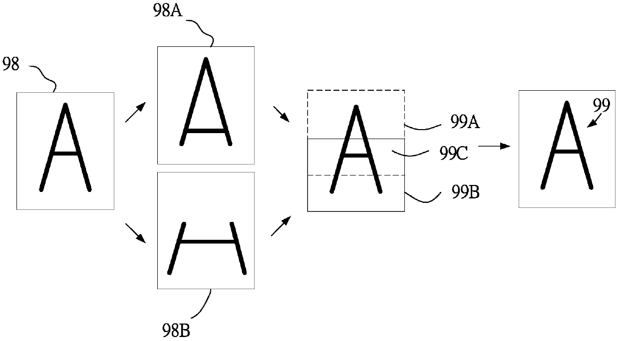
A technology of joining device and laser, applied in printing and other directions, can solve the problems of unclear alignment, 99C connection error, marking error, etc., and achieve the effect of preventing the phenomenon of match heads

Active Publication Date: 2019-03-29
新代科技(苏州)有限公司
View PDF8 Cites 4 Cited by
  • Summary
  • Abstract
  • Description
  • Claims
  • Application Information

AI Technical Summary

Problems solved by technology

The overlapping part 99C of the laser source track will be laser marked twice, so that the unclear place in the original marking process can be marked twice to make it clearer, and finally the actual marking pattern 99 is formed. The method uses the overlapping part of the laser source track to join the partition graphics to make the marking clear, but the overlapping part 99C of the las

Method used


Image

  • Laser marking partitioning joint device and method thereof
  • Laser marking partitioning joint device and method thereof
  • Laser marking partitioning joint device and method thereof

Examples


Embodiment Construction

[0046] The following will clearly and completely describe the technical solutions in the embodiments of the present invention with reference to the accompanying drawings in the embodiments of the present invention. Obviously, the described embodiments are only some, not all, embodiments of the present invention. The components of the embodiments of the invention generally described and illustrated in the figures herein may be arranged and designed in a variety of different configurations. Accordingly, the following detailed description of the embodiments of the invention provided in the accompanying drawings is not intended to limit the scope of the claimed invention, but merely represents selected embodiments of the invention. Based on the embodiments of the present invention, all other embodiments obtained by those skilled in the art without making creative efforts belong to the protection scope of the present invention.

[0047] It should be noted that like numerals and let...


PUM


Abstract

The invention relates to a laser marking partitioning joint device and method. The laser marking partitioning joint device comprises a laser marking device, a laser source device and a visual device,the laser marking device drives a laser source device, and the laser marking device comprises: a user interface for drawing graphics and import request data; an arithmetic module for outputting readable data according to graphics and request data; a galvanometer module for driving the laser source device; and a controller module for receiving readable data and data transmitted by the galvanometermodule, and carrying out interpolation on the readable data and the data transmitted by the galvanometer module to obtain the default value of connection graph parameters; the laser source device receives the default value of the connection graph parameters and marks the carrying out partition marking on a workpiece; and the visual device has an image capturing module and an image comparison module. The image capturing module captures the partition marking image on the workpiece, and the image comparison module carries comparison and returns the image discrimination result to the user interface. The partition marking is used to correct the partition marking image, and the visual device determines whether the partition marking image is good or bad.

Description

technical field [0001] The invention relates to a laser marking partition bonding device and a method thereof, in particular to a laser marking partition bonding device for laser marking using an image partition bonding method. Background technique [0002] At present, the laser marking machine forms text, pattern and other marks on the surface of the workpiece by means of laser. Compared with the traditional mechanical engraving or chemical etching method, it has the advantages of high precision, fast speed and permanent marks. Therefore, in the industry, especially in the integrated circuit industry, high-precision and high-volume IC marks are required, so laser marking technology and devices are really important in the industry. [0003] A general laser marking machine includes a laser source, a control card and a galvanometer module. The laser source emits laser light. In order to match the marking characteristics of fast speed and high precision, the laser in the laser ...

Claims


Application Information

Patent Timeline
IPC IPC(8): B41J2/47
CPCB41J2/471
Inventor 于宁祥柯幸宜
Owner 新代科技(苏州)有限公司
Why Eureka
Try Eureka