
New-energy security anti-theft charging pile

A charging pile and anti-theft technology, which is applied in the field of new energy security and anti-theft charging piles, can solve the inconvenience of moving, repairing and replacing new energy charging piles, the production of new energy charging piles cannot keep up, and the installation of new energy charging piles is not suitable. Problems, to achieve the effect of increasing anti-theft security, easy to move, and meeting market demand

Inactive Publication Date: 2019-03-29
崔昊男 +1
View PDF0 Cites 6 Cited by
  • Summary
  • Abstract
  • Description
  • Claims
  • Application Information

AI Technical Summary

Problems solved by technology

[0002] With the popularity of new energy electric vehicles, the market demand for new energy charging piles continues to increase. In order to meet the outdoor charging needs of new energy electric vehicles, the number of new energy charging piles to be built in my country is still very large; the existing new energy charging piles are generally With fixed installation, new energy charging piles need to be buried in the concrete foundation to achieve the purpose of anti-theft. However, since the production of new energy charging piles cannot keep up with the speed of installation, this installation method needs to transport new energy charging piles to the installation site After starting construction, it is not suitable for the installation of large quantities of new energy charging piles, which affects the early stage of installation, and it is not convenient for the movement, maintenance and replacement of new energy charging piles after installation, which cannot meet the actual needs, so we invented A new energy safe and anti-theft charging pile

Method used


Image

  • New-energy security anti-theft charging pile
  • New-energy security anti-theft charging pile
  • New-energy security anti-theft charging pile

Examples


Embodiment Construction

[0014] In order to make the purpose, technical solutions and advantages of the embodiments of the present invention clearer, the technical solutions in the embodiments of the present invention will be clearly and completely described below in conjunction with the drawings in the embodiments of the present invention. Obviously, the described embodiments It is a part of embodiments of the present invention, but not all embodiments. Based on the embodiments of the present invention, all other embodiments obtained by persons of ordinary skill in the art without creative efforts fall within the protection scope of the present invention.

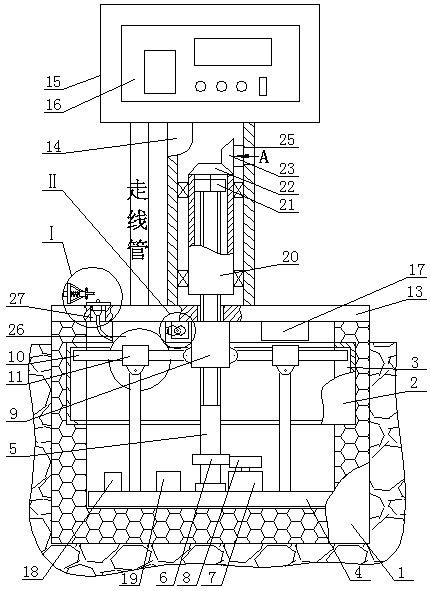
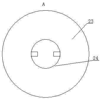
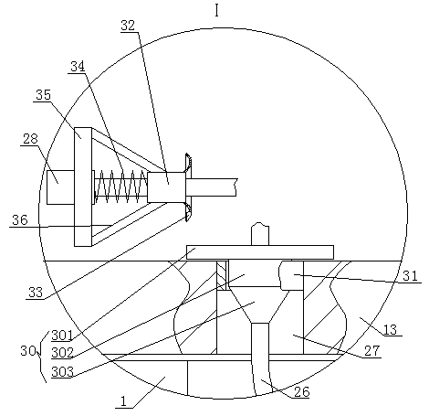
[0015]A new energy safe and anti-theft charging pile, as shown in the figure, includes a base 1. The base 1 is a concrete pouring platform with a hollow interior and an open top side. The middle part of the inner side of the base 1 is embedded with an annular fixing plate 2, which is fixed The inner side of the plate 2 is provided with an annular ...


PUM


Abstract

A new-energy security anti-theft charging pile comprises a base. An annular fixing plate is embedded in the middle of the inner side of the base, an annular fixing groove is formed in the inner side of the annular fixing plate, a supporting plate is movably installed at the bottom of the base, the middle of the top surface of the supporting plate is in bearing connection with the lower end of a lead screw, a first gear is fixedly installed at the lower portion of the periphery of the lead screw, a motor is fixedly installed at the left side of the top of the supporting plate, a second gear isfixedly installed at the upper end of a rotating shaft of the motor, the second gear is meshed and matched with the first gear, a nut is installed at the upper portion of the periphery of the lead screw through threads, the inner ends of a plurality of fixing rods are evenly hinged to the periphery of the nut, linear bearing sleeve the middle portions of the fixing rods respectively, the outer ends of the fixing rods are located in the fixing groove, and the bottom sides of the linear bearings are hinged to the upper ends of supporting rods respectively. Valuable electronic devices in the new-energy charging pile are placed in the base and protected in the base through an annular anti-theft plate, and the anti-theft security of the new-energy charging pile is improved.

Description

technical field [0001] The invention belongs to the field of new energy charging piles, in particular to a new energy safe and anti-theft charging pile. Background technique [0002] With the popularity of new energy electric vehicles, the market demand for new energy charging piles continues to increase. In order to meet the outdoor charging needs of new energy electric vehicles, the number of new energy charging piles to be built in my country is still very large; the existing new energy charging piles are generally With fixed installation, new energy charging piles need to be buried in the concrete foundation to achieve the purpose of anti-theft. However, since the production of new energy charging piles cannot keep up with the speed of installation, this installation method needs to transport new energy charging piles to the installation site After starting construction, it is not suitable for the installation of large quantities of new energy charging piles, which affects...

Claims


Application Information

Patent Timeline
IPC IPC(8): B60L53/31B60L53/16B60L53/18
CPCY02T10/70Y02T10/7072Y02T90/12Y02T90/14
Inventor 崔昊男崔文凯
Owner 崔昊男
Learn More