
Roller bearing transfer module and roller bearing transfer machine

A technology of fulai wheel and transfer machine, which is applied to the field of fulai wheel transfer module and fulai wheel transfer machine, can solve the problems such as the inability to transport the box body smoothly and the insufficient power of the driven wheel group, so as to reduce the probability of insufficient power, Guaranteed smooth delivery

Pending Publication Date: 2019-03-29
BLUESWORD INTELLIGENT TECH CO LTD
View PDF0 Cites 1 Cited by
  • Summary
  • Abstract
  • Description
  • Claims
  • Application Information

AI Technical Summary

Problems solved by technology

[0004] The purpose of the present invention is to provide a freewheel transfer module and a freewheel transfer machine, so as to alleviate the technical problem that the freewheel transfer machine in the prior art is prone to insufficient power of the driven wheel assembly, which leads to the inability to smoothly transport the box

Method used


Image

  • Roller bearing transfer module and roller bearing transfer machine
  • Roller bearing transfer module and roller bearing transfer machine

Examples


Embodiment 1

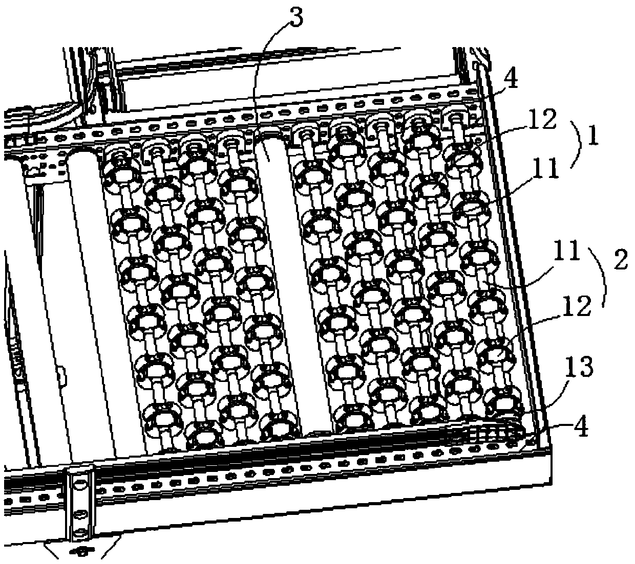
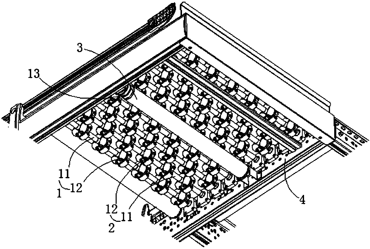
[0028] Such as figure 1 and figure 2 As shown, the embodiment of the present invention provides a Fulai wheel transfer module, including a first driven wheel set 1, a second driven wheel set 2 and an electric roller 3 arranged parallel to each other. The electric roller 3 has one and is connected to the first The driven wheel set 1 and the second driven wheel set 2 are transmission connected; the first driven wheel set 1 and the second driven wheel set 2 all include a sleeve 11 and a plurality of freewheels 12 fixed on the sleeve 11 at equal intervals. The driven wheel set 1 is adjacent to the second driven wheel set 2 or the electric roller 3, and the second driven wheel set 2 is adjacent to the first driven wheel set 1 or the electric roller 3. The Freewheels 12 and the Freewheels 12 on the adjacent second driven wheel set 2 are arranged in an interlaced manner in the axial direction of the casing 11 .

[0029] In the free wheel transfer module provided by the embodiment ...

Embodiment 2

[0050] Such as figure 1 As shown, the embodiment of the present invention provides a freewheel transfer machine, including at least one freewheel transfer module as described above.

[0051] The technical advantages of the freewheel transfer machine provided by the present invention are the same as those of the abovementioned freewheel transfer module, and will not be repeated here.

[0052] It is worth noting that when multiple Freewheel transfer modules are used, this embodiment preferably sets the number of the first driven wheel group 1 and the second driven wheel group 2 in the multiple Freewheel transfer modules and the ratio of the electric roller 3 The arrangements are all the same; alternatively, the number of the first driven wheel group 1 and the second driven wheel group 2 in the Fulai wheel transfer module can also be set to be different but the arrangement method is the same as that of the electric roller 3. This setting is more flexible and more efficient. It i...


PUM


Abstract

The invention provides a roller bearing transfer module and a roller bearing transfer machine, and relates to the technical field of conveying equipment. The roller bearing transfer module comprises one or more first driven wheel groups, one or more second driven wheel groups and one electric roller, wherein the first driven wheel groups and the second driven wheel groups are arranged parallel toeach other; the electric roller is in transmission connection with the first driven wheel groups and the second driven wheel groups; both the first driven wheel groups and the second driven wheel groups comprise sleeves and a plurality of roller bearings; the roller bearings are fixed on the sleeves in an equal spacing manner; the first driven wheel groups are arranged adjacent to the second driven wheel groups or the electric roller; the second driven wheel groups are arranged adjacent to the first driven wheel groups or the electric roller; and the bearing rollers on the first driven wheel groups and those on the adjacent second driven wheel groups are staggered in the axial directions of the sleeves. Consequently, the technical problem that a conventional roller bearing transfer machinecannot convey a box body smoothly because driven wheel groups easily lack the wheel power can be solved.

Description

technical field [0001] The invention relates to the technical field of conveying equipment, in particular to a Freewheel transfer module and a Freewheel transfer machine. Background technique [0002] The Fulai wheel transfer machine is a kind of conveyor that uses rollers for transportation. It is mostly used in the curved part or the diversion and confluence part of the conveying system. It has the characteristics of light structure and is widely used in frequent moving and light weight conveyors. For special occasions, such as logistics equipment, telescopic machines, and equipment that are often temporarily transported in the field, etc., it has the characteristics of low cost, durable, not easy to damage, and beautiful appearance. In addition, it requires the bottom surface of the conveyed items to be flat, such as pallets. It is not suitable for conveying uneven bottom surfaces (such as ordinary turnover boxes) and soft bottoms (such as cloth parcels, etc.). [0003]...

Claims


Application Information

Patent Timeline
IPC IPC(8): B65G47/64
CPCB65G47/64
Inventor 张贻弓沈长鹏刘鹏吴耀华张小艺蒋霞
Owner BLUESWORD INTELLIGENT TECH CO LTD
Learn More