Cable pulley assembly

A pulley and component technology, applied in the direction of overhead lines/cable equipment, etc., can solve the problems of offset, affecting the quality of the cable, changing the direction, etc., to achieve the effect of ensuring the transmission effect and the smoothness of the conveying

Active Publication Date: 2021-11-23
大唐长春热力有限责任公司
View PDF5 Cites 0 Cited by
  • Summary
  • Abstract
  • Description
  • Claims
  • Application Information

AI Technical Summary

Problems solved by technology

[0002] In the installation process of existing electric power engineering, when the cables are conveyed or threaded, they need to be guided and conveyed by cable pulleys to prevent them from rubbing against surrounding objects, causing damage to the skin and affecting the quality of the cables;
[0003] However, the conveying position of the existing cable trolley is fixed, and it cannot adjust the conveying direction and conveying position, so that when it conveys the guiding cable, it cannot change the direction according to the fine-tuning of the direction of the cable during conveying, such as when two threading When there is a deviation between the holes, the position of the cable will be shifted when passing from one hole to another hole, and the position of the tackle in the original hole needs to be changed, which makes loading and unloading troublesome and inefficient

Method used


Image

  • Cable pulley assembly
  • Cable pulley assembly
  • Cable pulley assembly

Examples


Embodiment

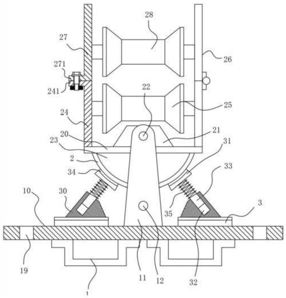
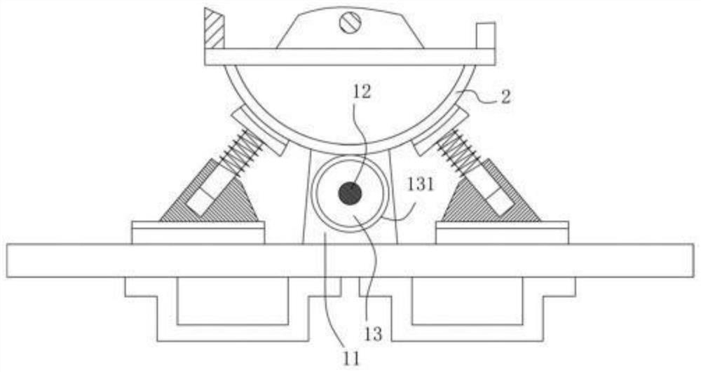
[0021] Example: see Figure 1 to Figure 3 As shown, a cable trolley assembly includes a base 10, the front and rear parts of the top surface middle of the top plate of the base 10 are fixed with vertical support plates 11, and the lower parts of the two vertical support plates 11 are fixed with lower The connecting shaft 12, the middle part of the lower connecting shaft 12 is hinged with the lower roller 13 through the bearing, the upper fixing plate 20 is between the two vertical support plates 11, and the upper fixing block 21 is fixed on the top surface middle part of the upper fixing plate 20, and the upper fixing The middle part of block 21 is hinged with upper connecting shaft 22 by bearing, and upper connecting shaft 22 is fixed on two vertical supporting plates 11, and the bottom surface middle part of upper fixing plate 21 is fixed with arc-shaped block 23, and the side wall of arc-shaped block 23 is tight. Paste the side wall of the roller 13;

[0022] The left and ...


PUM


Abstract

The invention discloses a cable pulley assembly which comprises a base, vertical supporting plates are fixed to the front portion and the rear portion of the middle of the top face of a top plate of the base, a lower connecting shaft is fixed to the lower portions of the two vertical supporting plates, a lower rolling wheel is hinged to the middle of the lower connecting shaft through a bearing, and an upper fixing plate is located between the two vertical supporting plates. An upper fixing block is fixed to the middle of the top face of the upper fixing plate, an upper connecting shaft is hinged to the middle of the upper fixing block through a bearing, the upper connecting shaft is fixed to the two vertical supporting plates, an arc-shaped block is fixed to the middle of the bottom face of the upper fixing plate, and the side wall of the arc-shaped block is tightly attached to the side wall of the lower roller; and certain fine adjustment can be carried out according to the position of the cable in the conveying process, the conveying effect and conveying smoothness are guaranteed, and a tackle does not need to be installed again.

Description

technical field [0001] The invention relates to the technical field of electric power engineering equipment, in particular to a cable pulley assembly. Background technique [0002] In the installation process of existing electric power engineering, when the cables are conveyed or threaded, they need to be guided and conveyed by cable pulleys to prevent them from rubbing against surrounding objects, causing damage to the skin and affecting the quality of the cables; [0003] However, the conveying position of the existing cable trolley is fixed, and it cannot adjust the conveying direction and conveying position, so that when it conveys the guiding cable, it cannot change the direction according to the fine-tuning of the direction of the cable during conveying, such as when two threading When there is a deviation between the holes, its position will be offset when its cables pass from one hole to another, and the position of the tackle in the original hole needs to be changed...

Claims


Application Information

Patent Timeline
Patent Type & Authority Applications(China)
IPC IPC(8): H02G1/04
CPCH02G1/04
Inventor 不公告发明人
Owner 大唐长春热力有限责任公司
Why Eureka
Try Eureka