Elevator device

A technology of elevators and lifting bodies, applied in transportation, packaging, elevators, etc., can solve the problems of large buffers, increased assumed collision speeds, and changes in inertial forces, and achieve the effect of longer suppression time

Active Publication Date: 2019-04-02
MITSUBISHI ELECTRIC CORP
View PDF7 Cites 3 Cited by
  • Summary
  • Abstract
  • Description
  • Claims
  • Application Information

AI Technical Summary

Problems solved by technology

[0005] Here, a buffer is provided in the pit at the lower end of the hoistway to decelerate the car when it cannot be decelerated by an emergency stop device. However, the usual overspeed governor has the following problems: Since the operation is performed at a fixed speed regardless of the detected speed, the assumed collision speed of the buffer increases according to the rated speed, the size of the bu

Method used


Image

  • Elevator device
  • Elevator device
  • Elevator device

Examples


Embodiment approach 1

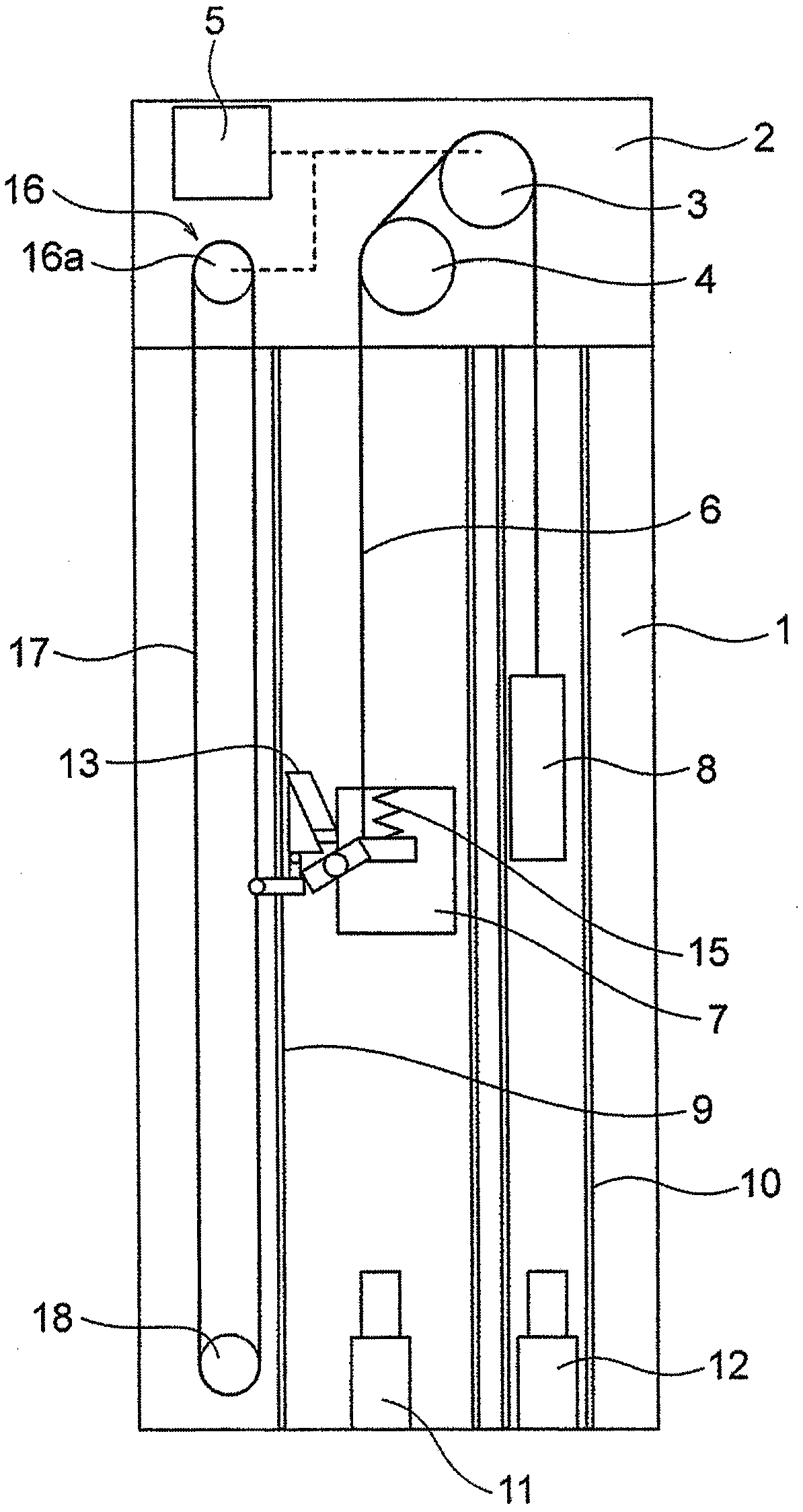
[0054] figure 1 It is a block diagram showing the elevator apparatus according to Embodiment 1 of the present invention. In the figure, a machine room 2 is arranged on the upper part of the hoistway 1 . A traction machine 3 and a deflector pulley 4 are arranged in the machine room 2 . The hoisting machine 3 has: a driving sheave; a hoisting machine motor that rotates the driving sheave; and a hoisting machine brake (electromagnetic brake) that brakes the rotation of the driving sheave.

[0055] The traction machine brake has: a brake sheave (drum or disc), which is coaxially combined with the drive sheave; a brake shoe, which contacts or separates from the brake sheave; and a brake spring, which directs the brake shoe toward the brake The brake wheel is pressed to apply the braking force; the electromagnet, which resists the brake spring, moves the brake shoe away from the brake wheel, thereby releasing the braking force.

[0056] A suspension body 6 is wound around the tra...

Embodiment approach 2

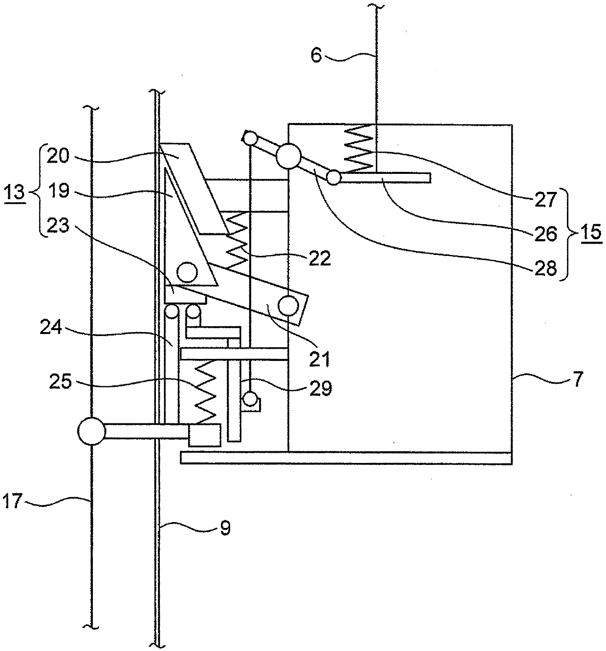
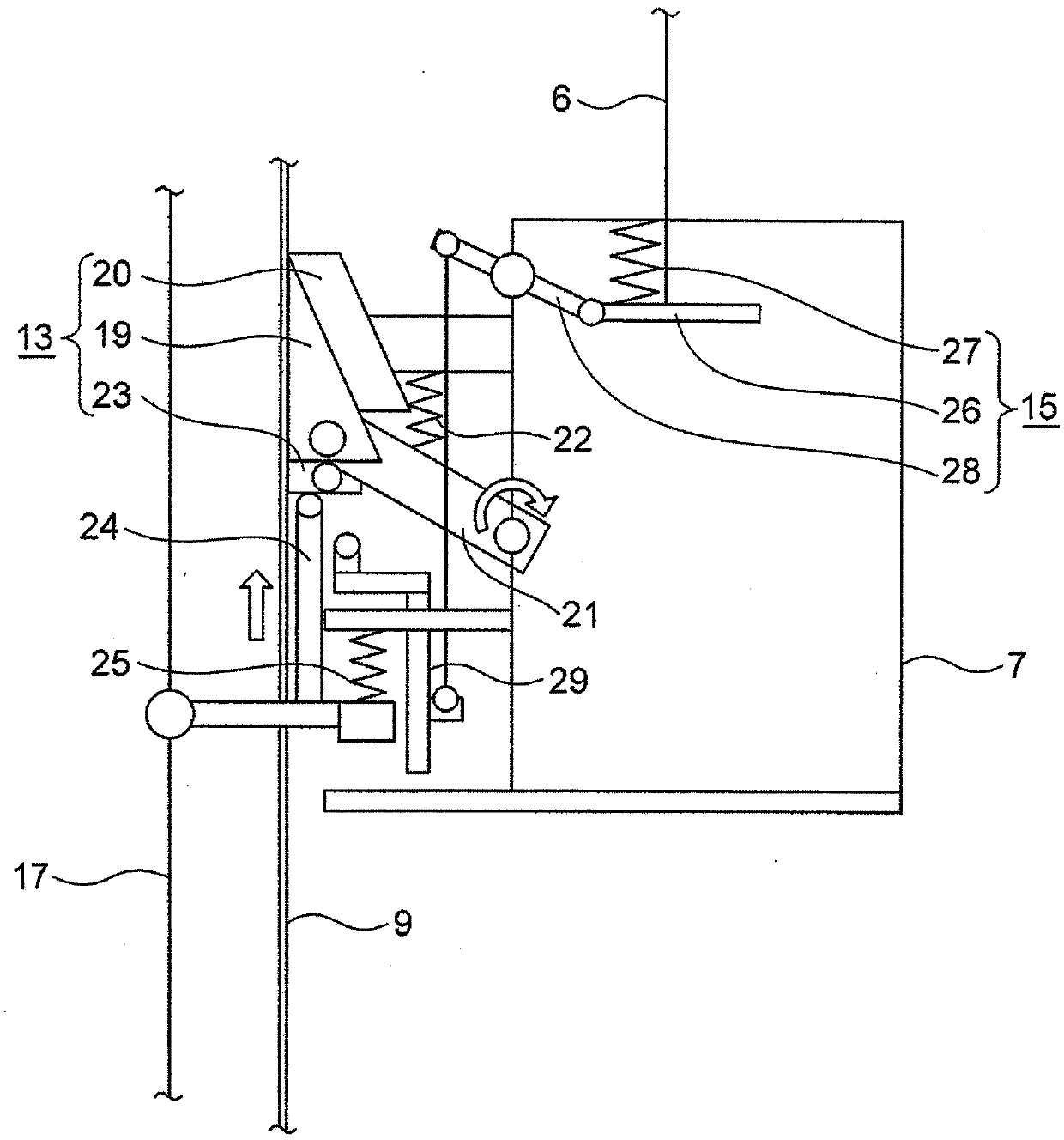
[0081] Next, Embodiment 2 of the present invention will be described. In addition, this second embodiment is the same as the above-mentioned first embodiment except for the parts described below. Figure 7 It is an enlarged view of the urging part receiving part of the structure in which the front end of the link retracts by compression in Embodiment 2, and is a view showing a locked state. Figure 8 It is an enlarged view of the urging part receiving part of the structure in which the front end of the link retracts by compression in Embodiment 2, and is a view showing a lock release state.

[0082] In Embodiment 1, instead of providing the vibration suppressing spring 22 on the link linked with the brake, a locking mechanism 33 is provided inside the urging part receiving part 23, and the first urging part 24 and the second urging part 24 are connected to each other. When the parts 29 are all in the initial position, due to the dead weight of the link of the locking mechanis...

Embodiment approach 3

[0089] Next, Embodiment 3 of the present invention will be described. In addition, this Embodiment 3 is the same as the said Embodiment 1 or 2 except the part demonstrated below. Figure 11 It is an enlarged view of the urging part receiving part 23 of Embodiment 3, and is a figure showing the state before engaging. Figure 12It is an enlarged view of the urging part receiving part 23 of Embodiment 3, and is a figure showing the time when the speed governor rope side is pulled up (the state in which the engaging mechanism operates).

[0090] In the contact portion between the brake member and the urging portion of Embodiment 1, a groove 41 is provided in the urging portion, and a link 40 is provided so that the urging portion can be freely displaced in an initial state. , when the force application part is displaced upward once and enters the brake receiving part, the connecting rod 40 rotates on the brake support part and engages with the groove 41 of the force application p...


PUM


Abstract

Provided is an elevator device that includes a wedge-shaped braking element for gripping a guide rail on a lifting body. A speed governor rope is installed in a hoist way in parallel with a suspensionbody of the lifting body. The elevator device is provided with a first biasing part for biasing the braking element upward by gripping the speed governor rope in the speed governor in the case wherethe lifting body has abnormally accelerated, and a second biasing part for biasing the braking element upward by utilizing the motion generated by the falling of the lifting body at the time of breakage of the suspension body. At least one of the first biasing part and the second biasing part is separated from the braking element.

Description

technical field [0001] The present invention relates to an elevator installation. Background technique [0002] In the rope elevator, the car and the counterweight use the main rope, and are connected into a bucket shape by means of a traction machine installed at the upper end of the hoistway or in the machine room above the hoistway, and the car moves up and down by the rotation of the traction machine. The hoisting machine is provided with a brake, and when an abnormality such as abnormal acceleration of the elevator is detected, the hoisting machine brake operates to safely stop the car. [0003] In addition, as a safety device when the brake of the traction machine does not work and the car accelerates downward due to breakage of the main rope or slipping between the traction machine and the main rope, etc., a grip guide rail is provided on the car. An emergency stop device that decelerates the car. [0004] In order to drive the emergency stop device, the speed gover...

Claims


Application Information

Patent Timeline
IPC IPC(8): B66B5/04
CPCB66B5/04B66B5/28B66B5/044B66B5/18B66B5/26
Inventor 福井孝太郎渡边诚治白石直浩
Owner MITSUBISHI ELECTRIC CORP
Why Eureka
Try Eureka