
Method and arrangement for acquiring image data

A technology for acquiring images and image data, applied in the field of acquiring image data and layout, it can solve the problems of weakening signal strength and reducing the signal-to-noise ratio, and achieve the effect of reducing the load

Active Publication Date: 2019-04-02
CARL ZEISS MICROSCOPY GMBH
View PDF9 Cites 0 Cited by
  • Summary
  • Abstract
  • Description
  • Claims
  • Application Information

AI Technical Summary

Problems solved by technology

Inevitably, however, this requires splitting the optical signal over multiple channels and multiple photodetectors, which represents an additional source of noise
Signal-to-noise ratio (SNR) is further reduced by the signal strength in the individual channels, which is weakened by segmentation

Method used


Image

  • Method and arrangement for acquiring image data
  • Method and arrangement for acquiring image data

Examples


Embodiment Construction

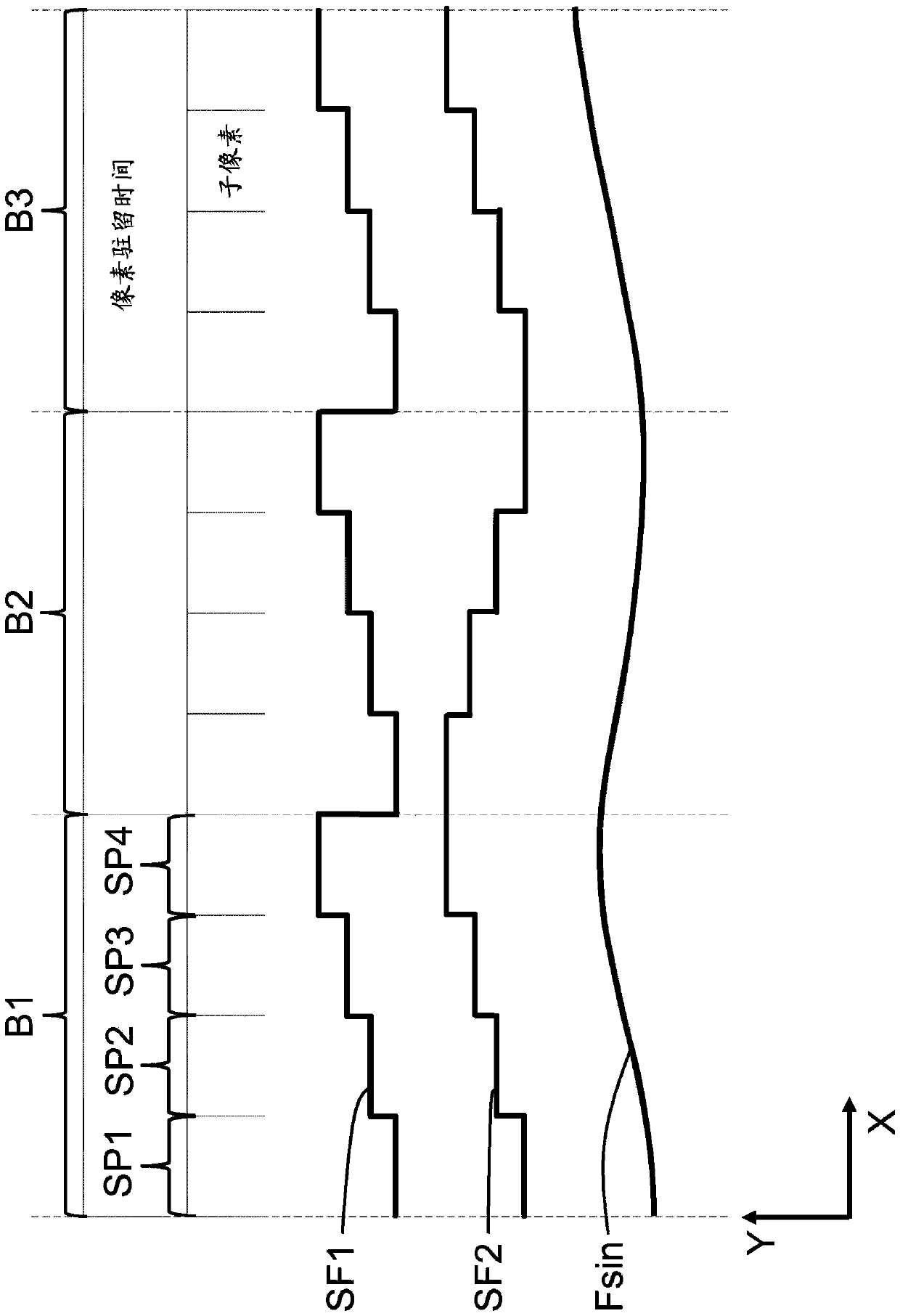
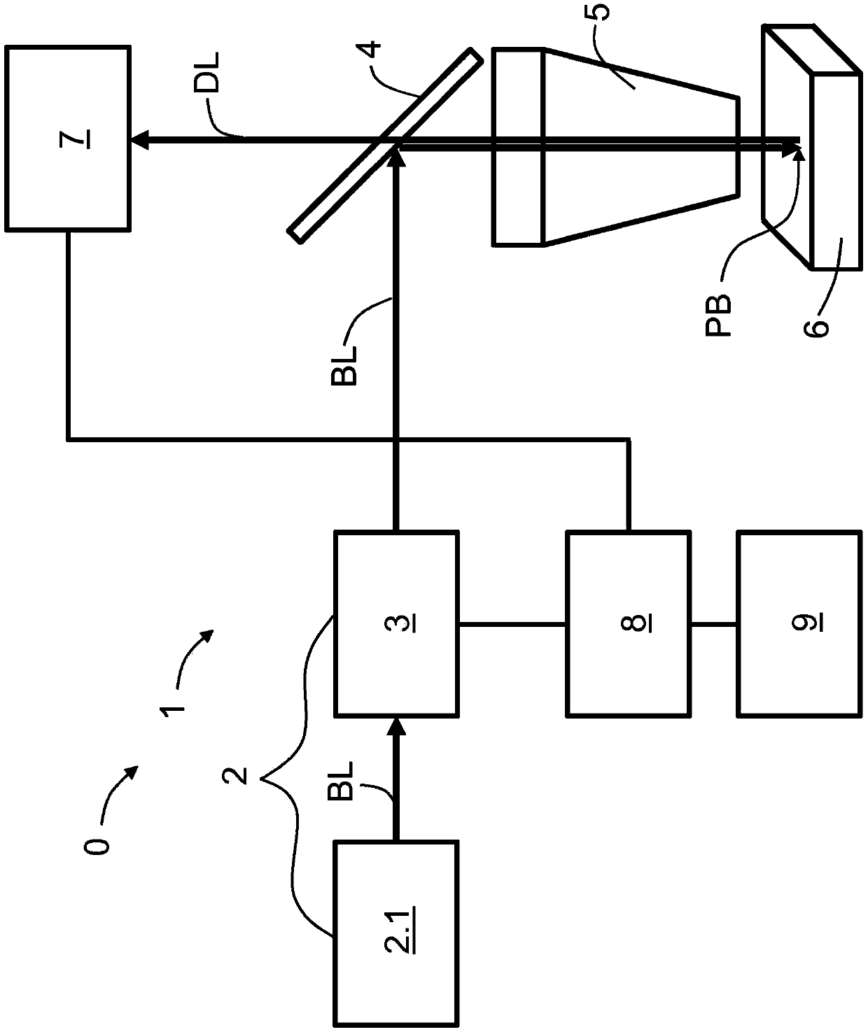
[0038] figure 1 The graph with the x-axis as the time axis schematically shows three consecutive lighting intervals B1 to B3. During each illumination interval B1 to B3 (also referred to as pixel dwell time), the pixel area PB is illuminated with four illumination lights BL having respective different intensities over the same duration (cf. figure 2 ), denoted as first to fourth sub-pixels SP1 to SP4 for the first illumination interval B1.

[0039] figure 1 An overview of three possible function types that can be used in the method according to the invention is shown as an example. The function value of the function is plotted in the direction of the y-axis Y.

[0040] The first step function SF1 is stepped up with the duration of the illumination intervals B1 to B3, wherein each step corresponds to a respective sub-pixel SP1 to SP4 in the relevant illumination interval B1 to B3 with respect to the temporal position and its duration. At the end of each lighting interval B...


PUM


Abstract

The invention relates to a method for acquiring image data, in which a pixel region (PB) of a sample (6) to be imaged is illuminated in a plurality of illumination events, with illumination light (BL)of a respectively selected intensity, which intensities differ from one another, and subsequently detection light (DL) which respectively comes from the pixel region (PB) is acquired for each of theintensities as image data items of a subpixel (SP1 to SP4) and resulting image data items of the pixel region (PB) are acquired from the number of detected image data items of the subpixel (SP1 to SP4). According to the invention, the illumination events are triggered successively. The image data of all the subpixels (SP1 to SP4) of the pixel region (PB) are acquired before a further pixel region(PB) is illuminated. The invention also relates to an arrangement (1) for acquiring image data items and to a microscope (0) with such an arrangement (1).

Description

technical field [0001] The invention relates to methods and arrangements for acquiring images according to the preambles of the independent claims. Background technique [0002] For the pixel-by-pixel acquisition of image data, for example, the method of dynamic image recording is used, in which multiple recordings of the sample or sample area are conventionally illuminated with different illumination intensities, the detection light emitted from the sample is detected and the image data acquired in this way Cancel each other out. [0003] By means of multiple single image recordings with different exposure times, both dark and bright image areas can be measured separately with a good signal-to-noise ratio. Said image regions can then be calculated to form an overall image with enhanced dynamics, where both bright and dark regions are rendered with high contrast (known as High Dynamic Range Imaging; HDRI; A. Bell et al.: "High Dynamic Range Images "High Dynamic Range Image...

Claims


Application Information

Patent Timeline
Patent Type & Authority Applications(China)
IPC IPC(8): G02B21/00H04N3/10H04N5/235
CPCH04N3/10G02B21/16G02B21/367H04N23/741G02B21/0032G02B21/0076
Inventor M.李德克J.哈尔斯特里希
Owner CARL ZEISS MICROSCOPY GMBH
Features
  • Generate Ideas
  • Intellectual Property
  • Life Sciences
  • Materials
  • Tech Scout
  • Unparalleled Data Quality
  • Higher Quality Content
  • 60% Fewer Hallucinations
Learn More