Hydraulic moving expansion sleeve positioning mechanism

A technology of positioning mechanism and expansion sleeve, which is applied in the direction of positioning device, expanding mandrel, metal processing machinery parts, etc., can solve the problems of poor positioning accuracy and stability of positioning mechanism, workpiece clamping, fixed positioning pin and other problems, and achieve The effect of improving positioning accuracy and stability

Pending Publication Date: 2019-04-05
无锡倍安杰机械科技有限公司
View PDF0 Cites 0 Cited by
  • Summary
  • Abstract
  • Description
  • Claims
  • Application Information

AI Technical Summary

Problems solved by technology

[0002] In the design of machining fixtures, it often happens that the positioning holes at both ends of the workpiece need to be positioned, but the fixed positioning pins cannot realize the clamping of the workpiece. In addition, the positioning accuracy and stability of ordinary positioning mechanisms are also poor. Therefore, it is necessary to design A mobile positioning pin mechanism to solve such problems conveniently

Method used


Image

  • Hydraulic moving expansion sleeve positioning mechanism
  • Hydraulic moving expansion sleeve positioning mechanism
  • Hydraulic moving expansion sleeve positioning mechanism

Examples


Embodiment Construction

[0016] combine Figure 1 to Figure 4 , which describes the first specific embodiment of the present invention in detail, but does not limit the claims of the present invention in any way.

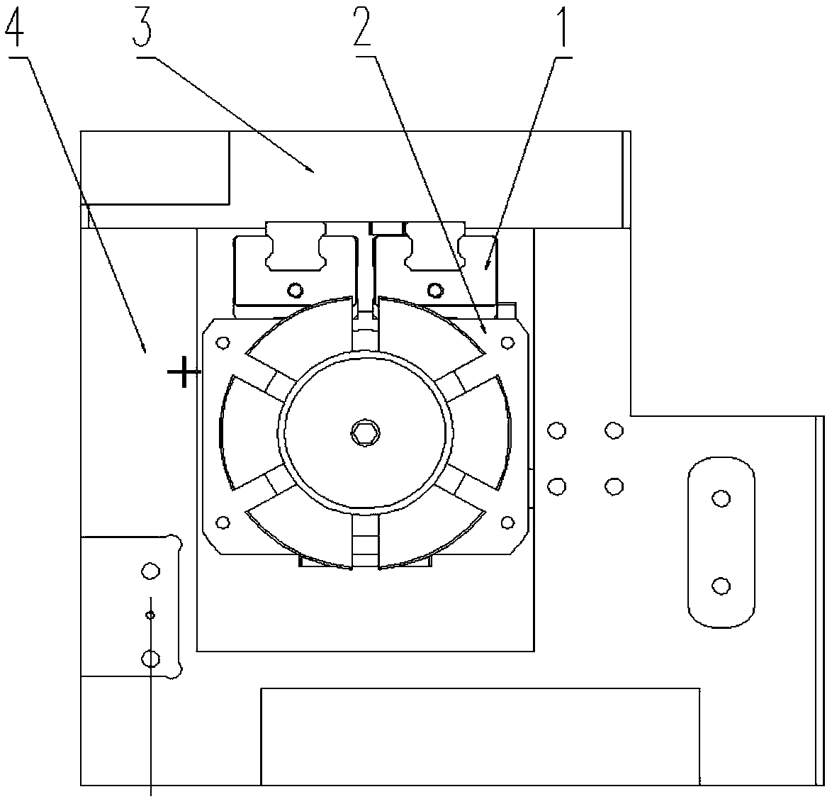
[0017] Such as Figure 1 to Figure 4 As shown, a hydraulically movable expansion sleeve positioning mechanism includes a linear slide rail 1, a slide rail mounting plate 3, a fixed seat 4, an oil cylinder 9 and an expansion sleeve positioning mechanism, and a slide rail mounting plate 3 is installed on the fixed base 4 , the slide rail mounting plate 3 is installed with a linear slide rail 1, the expansion sleeve positioning mechanism is installed on the linear slide rail 1, and can move back and forth, and the oil cylinder 9 drives the expansion sleeve positioning mechanism in a straight line Move back and forth on the slide rail 1;

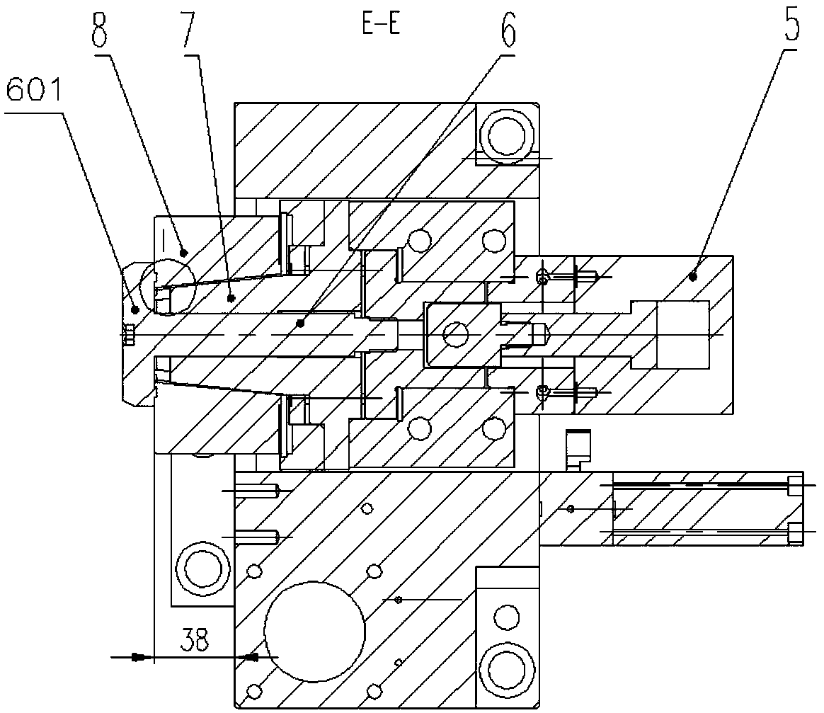
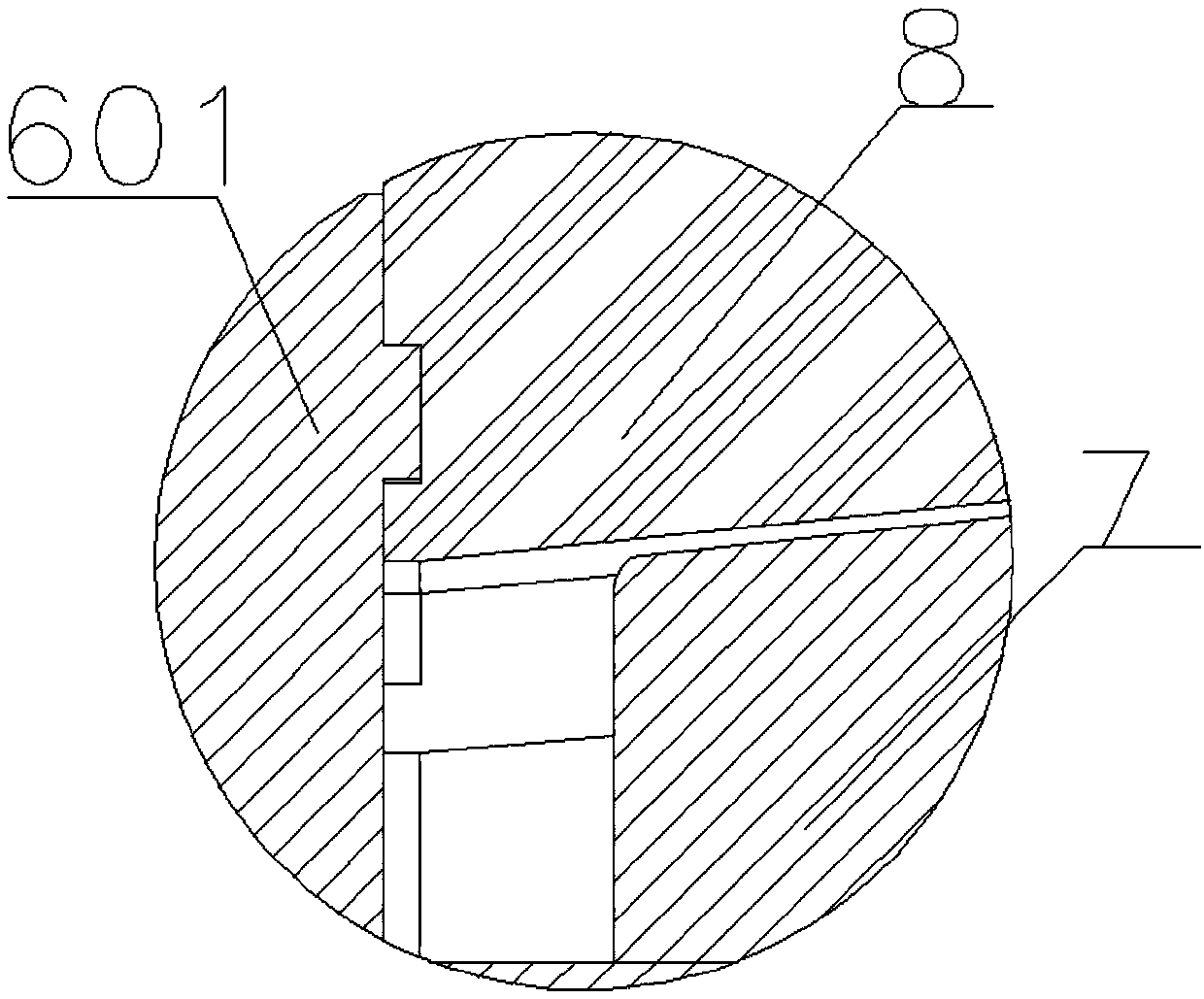
[0018] The expansion sleeve positioning mechanism includes an expansion sleeve oil cylinder 5, a floating pull rod 6, a cone seat 7 and an expansion sleeve...


PUM


Abstract

The invention relates to a hydraulic moving expansion sleeve positioning mechanism which comprises a linear sliding rail, a sliding rail installation plate, a fixing seat, an oil cylinder and an expansion sleeve positioning mechanism. The oil cylinder drives the expansion sleeve positioning mechanism to move front and back in a reciprocating manner on the linear sliding rail. The expansion sleevepositioning mechanism comprises an expansion sleeve oil cylinder, a floating pull rod, a taper seat and an expansion sleeve. The expansion sleeve oil cylinder drives the floating pull rod to move. A circular truncated cone is arranged at the front end of the floating pull rod and drives the expansion sleeve to move along the taper face of the taper seat. By means of the hydraulic moving expansionsleeve positioning mechanism, during workpiece clamping, the oil cylinder drives the expansion sleeve positioning mechanism to overall move forwards and retreat backwards through a connecting block toachieve workpiece avoiding, in addition, the expansion sleeve oil cylinder drives the floating pull rod and the expansion sleeve to contract back so that the expansion sleeve can expand in the movingprocess, and the positioning precision and stability of workpiece clamping are improved through design of a positioning expansion workpiece hole.

Description

technical field [0001] The invention relates to the field of fixtures, in particular to a positioning mechanism for hydraulically movable expansion sleeves. Background technique [0002] In the design of machining fixtures, it often happens that the positioning holes at both ends of the workpiece need to be positioned, but the fixed positioning pins cannot realize the clamping of the workpiece. In addition, the positioning accuracy and stability of ordinary positioning mechanisms are also poor. Therefore, it is necessary to design A mobile positioning pin mechanism is provided to solve such problems conveniently. Contents of the invention [0003] Aiming at the problems in the prior art, the present invention provides a positioning mechanism for hydraulically movable expansion sleeves. [0004] In order to solve the above problems, the solution of the present invention is a hydraulically movable expansion sleeve positioning mechanism, including a linear slide rail, a slid...

Claims


Application Information

Patent Timeline
IPC IPC(8): B23Q3/00B23B31/42
CPCB23B31/42B23Q3/00B23Q2703/04
Inventor 尤梅洲靳加加肖照贤秦存永韩陶
Owner 无锡倍安杰机械科技有限公司
Why Eureka
Try Eureka