
Measuring, calibrating and positioning workbench structure

A workbench and machine base technology, applied in the direction of instruments, etc., can solve the problems affecting the structural applicability, restricting the positioning accuracy of the workbench structure, and affecting the stability of the structure, so as to avoid fatigue use and improve the positioning accuracy and stability.

Pending Publication Date: 2021-03-19
四川东华计量检测技术有限公司
View PDF0 Cites 0 Cited by
  • Summary
  • Abstract
  • Description
  • Claims
  • Application Information

AI Technical Summary

Problems solved by technology

[0003] However, the existing positioning worktable structure, as the workpiece placement end of the measuring instrument, the positioning accuracy of the workbench and the sliding movement structure are likely to affect the position adjustment structure of the workbench due to long-term use. The stability of the structure is affected in the middle, and it is difficult to accurately position the workbench by moving the sliding structure, which limits the positioning accuracy of the workbench structure to a certain extent and affects the applicability of the structure

Method used


Image

  • Measuring, calibrating and positioning workbench structure
  • Measuring, calibrating and positioning workbench structure
  • Measuring, calibrating and positioning workbench structure

Examples


Embodiment Construction

[0017] In order to have a clearer understanding of the technical features, purposes and effects of the present invention, the specific implementation manners of the present invention will now be described with reference to the accompanying drawings.

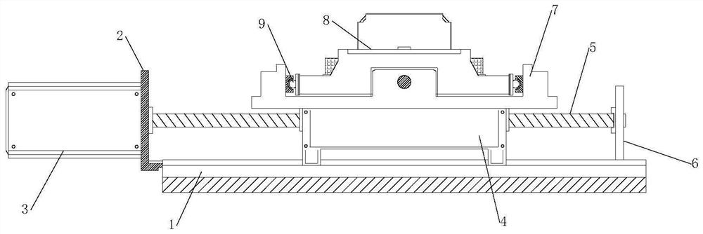
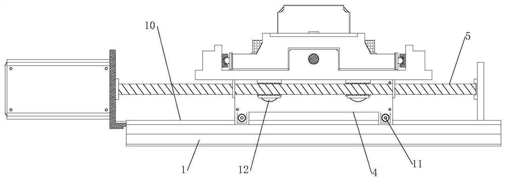
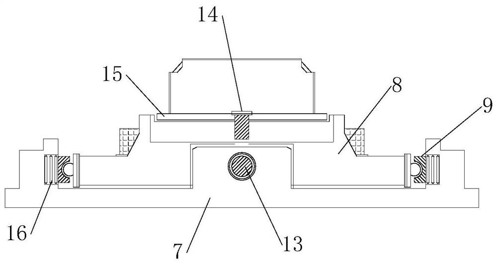
[0018] Examples such as figure 1 , figure 2 , image 3 As shown, a measurement calibration positioning workbench structure includes a lower machine base 1, and the front and rear ends of the upper surface of the lower machine base 1 are protrudingly provided with organic rails 10. There is an L-shaped clamping plate 2, which forms a concave structure with the cross section of the lower machine base 1 through the protruding machine rail 10, and the machine rail 10 slides in the axial direction so that the structural combination of the upper end of the lower machine base 1 is docked.

[0019] The L-shaped pallet 2 is slidingly connected with the machine rail 10, the left side of the L-shaped pallet 2 is fixedly provided with a m...


PUM


Abstract

The invention discloses a measuring, calibrating and positioning workbench structure, which relates to the technical field of instrument calibration. The structure comprises a lower base, wherein machine rails are convexly arranged at the front and rear ends of the upper surface of the lower base, the machine rails are embedded with the lower base, and L-shaped clamping plates are arranged at theleft ends of the inner sides of the machine rails; the L-shaped clamping plate is slidably connected with the machine rail, a motor is fixedly arranged on the left side of the L-shaped clamping plate,the right end of the motor is rotatably connected with an axial screw rod, and the axial screw rod penetrates through the L-shaped clamping plate; wheel rollers are symmetrically arranged on the leftside and the right side of the lower end of the chassis bearing; an upper machine base is welded to the upper end of the chassis bearing, a workbench panel is arranged in the middle of the upper endof the upper machine base in a sliding mode, the requirement for axial and radial translation between workbench combined structures is met through screws arranged in the axial direction and the radialdirection, and problems that an existing positioning workbench is low in precision and large in structural influence due to fatigue use are solved.

Description

technical field [0001] The invention relates to the technical field of instrument calibration, in particular to a measurement calibration positioning workbench structure. Background technique [0002] The positioning workbench is the product of the combination of precision machining instruments and electronic engineering. The upper guide rail and motor are assembled between the workbench base and the slide table to complete the workpiece material fixing of the measuring instrument and high-precision position adjustment. to meet measurement requirements; [0003] However, the existing positioning worktable structure, as the workpiece placement end of the measuring instrument, the positioning accuracy of the workbench and the sliding movement structure are likely to affect the position adjustment structure of the workbench due to long-term use. The stability of the structure is affected in the middle, and it is difficult to accurately position the workbench by moving the slid...

Claims


Application Information

Patent Timeline
IPC IPC(8): G01D18/00
CPCG01D18/00
Inventor 郑学成
Owner 四川东华计量检测技术有限公司
Learn More