
Tension leg type floating fan foundation and floating fan

A fan foundation and tension leg technology, applied to floating buildings, ships, etc., can solve problems such as unreasonable structural design of floating fans and affect the performance of floating fans, and achieve reduced overall steel consumption, light structure, and restraint The effect of high frequency vibration

Pending Publication Date: 2020-07-31
CHINA ENERGY ENG GRP GUANGDONG ELECTRIC POWER DESIGN INST CO LTD
View PDF0 Cites 4 Cited by
  • Summary
  • Abstract
  • Description
  • Claims
  • Application Information

AI Technical Summary

Problems solved by technology

[0004] The purpose of the present invention is to provide a tension leg type floating fan foundation, which is used to solve the technical problems that the structural design of the floating fan in the prior art is unreasonable and affects the performance of the floating fan

Method used


Image

  • Tension leg type floating fan foundation and floating fan
  • Tension leg type floating fan foundation and floating fan
  • Tension leg type floating fan foundation and floating fan

Examples


Embodiment Construction

[0032] The specific implementation manners of the present invention will be further described in detail below in conjunction with the accompanying drawings and embodiments. The following examples are used to illustrate the present invention, but are not intended to limit the scope of the present invention.

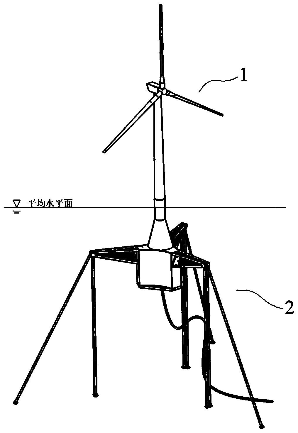
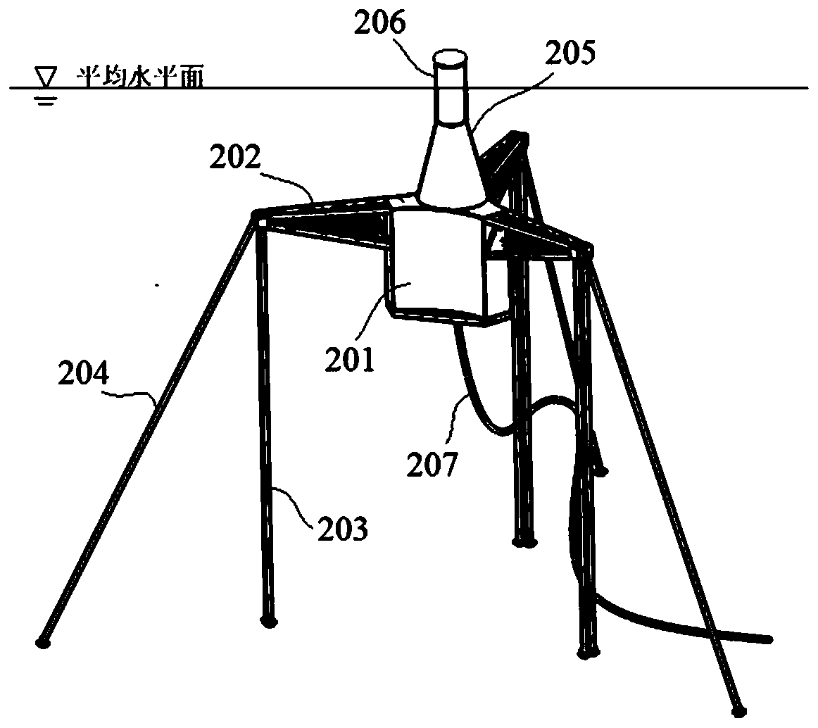
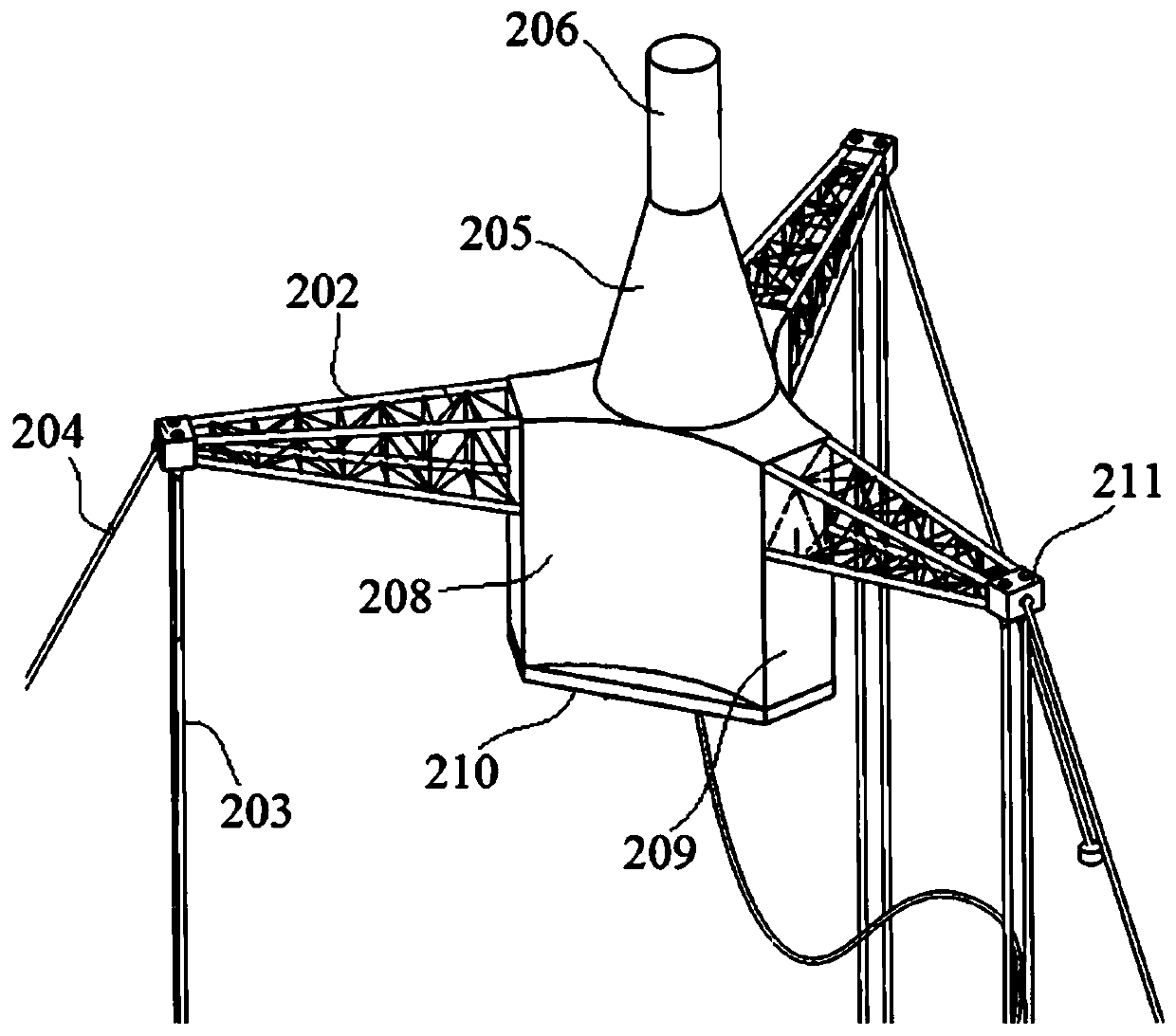
[0033] Such as Figure 1 to Figure 4 As shown, a floating fan according to the preferred embodiment of the embodiment of the present invention. The floating wind turbine includes wind power equipment 1 and the tension leg floating wind turbine foundation (hereinafter referred to as the wind turbine foundation 2) installed under the wind power equipment 1. The tension leg floating wind turbine foundation includes a main floating body structure 201, multiple truss beam structures 202 and connected The mooring mechanism at the free end of each truss beam structure 202, the mooring mechanism is used to connect with the seabed foundation, a plurality of mounting surfaces 209 a...


PUM


Abstract

The invention relates to a tension leg type floating fan foundation and a floating fan. The tension leg type floating fan foundation comprises a main floating body structure, a plurality of truss girder structures and mooring mechanisms connected to the free ends of the truss girder structures, wherein the mooring mechanism is used for being connected with a seabed foundation, a plurality of mounting surfaces and a plurality of resistance increasing surfaces are alternately distributed on the outer peripheral surface of the main floating body structure, the truss girder structures are mountedon the mounting surfaces in a one-to-one correspondence manner, and the resistance increasing surfaces are concave curved surfaces; a balance weight cabin and an adjusting cabin are arranged in the main floating body structure, the balance weight cabin is filled with a balance weight material, and the adjusting cabin is adjustably filled with an adjusting liquid used for controlling the draught depth of the main floating body structure; and the main floating body structure is further provided with damping plates protruding out of the resistance increasing surfaces. By the adoption of the tension leg type floating fan foundation and the floating fan, the attached water mass and hydrodynamic damping are increased, the self-stability of the main floating body structure is enhanced, and high-frequency vibration of the main floating body structure is restrained.

Description

technical field [0001] The invention relates to the technical field of offshore wind power generation, in particular to a foundation of a tension leg type floating fan and a floating fan. Background technique [0002] In recent years, with the increasing global demand for clean and renewable energy, wind energy has become one of the most commercialized renewable and clean energy technologies, showing a booming trend, and wind power is gradually moving from land to sea, From near sea to far sea. However, due to technical and economic problems, the application of fixed offshore wind turbines is limited to sea areas with a water depth of less than 50m. In order to obtain better wind energy and expand space resources for wind energy development, floating wind turbine technology has attracted extensive attention in recent years. [0003] At present, the tension leg floating body is one of the main basic forms of floating wind turbines. The traditional tension-leg floating body ...

Claims


Application Information

Patent Timeline
Patent Type & Authority Applications(China)
IPC IPC(8): B63B35/44
CPCB63B35/44B63B2035/446
Inventor 陈嘉豪裴爱国马兆荣杨敏冬林敬华庞程燕汤东升
Owner CHINA ENERGY ENG GRP GUANGDONG ELECTRIC POWER DESIGN INST CO LTD
Learn More