
Multi-mode clutch executer

A technology for clutches and actuators, applied in the direction of clutches, fluid-driven clutches, non-mechanical drive clutches, etc. Implementation and other issues, to achieve the effect of simple structure, reduce installation process requirements, and improve service life

Active Publication Date: 2018-08-14
江西鼎盛新材料科技有限公司
View PDF3 Cites 0 Cited by
  • Summary
  • Abstract
  • Description
  • Claims
  • Application Information

AI Technical Summary

Problems solved by technology

At present, multi-mode clutches are often used in engineering applications. The actuator structure is relatively complex, and one actuator contains multiple spring structures, but the spring structure has a certain fatigue limit, and when the same process spring operates in the same environment, its fatigue limit is also They are not the same, so it is easy to cause the multi-mode clutch actuator to be difficult to return, which will eventually affect the performance and service life of the multi-mode clutch actuator, thereby affecting the execution of the multi-mode clutch under various working conditions and affecting the driving performance of the car

Method used

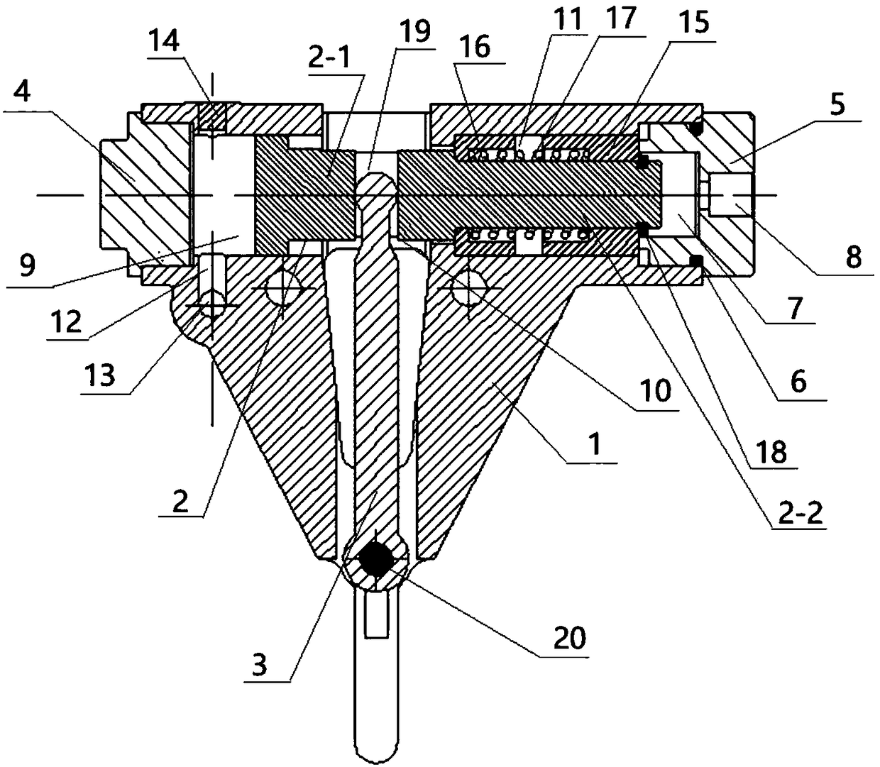

Image

  • Multi-mode clutch executer
  • Multi-mode clutch executer
  • Multi-mode clutch executer

Examples


Embodiment 1

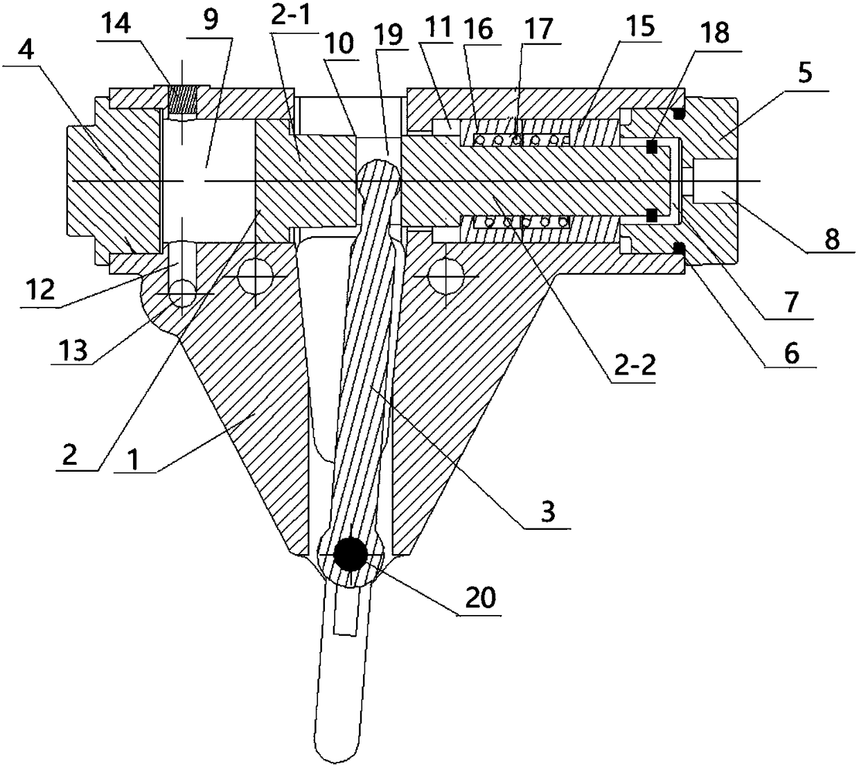
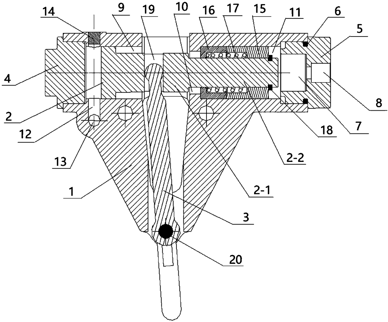
[0016] A multi-mode clutch actuator such as figure 1 As shown, it includes a cavity 1, an actuating plunger 2 and an actuating rod 3, the actuating plunger 2 includes a thick plunger rod 2-1 and a thin plunger rod 2-2, and the thick plunger rod 2-1 as a whole is T-shaped, the end of the thick plunger rod 2-the smaller diameter of the section is fixedly connected with the thin plunger rod 2-2, one end of the cavity 1 is plugged with the first screw plug 4, and the other end of the cavity is plugged with the first screw plug Two screw plugs 5, the second screw plug 5 is covered with an O-ring 6, the O-ring 6 is used to seal the oil passage between the cavity 1 and the second screw plug 5, the end surface of the second screw plug 5 facing inward A groove 7 is opened on the top, a first oil inlet hole 8 is opened on the second screw plug 5 and the first oil inlet hole 8 communicates with the groove 7, and the inside of the cavity 1 is from the first screw plug 4 to the second scre...

Embodiment 2

[0022] A multi-mode clutch actuator, the structure of which is similar to that of the multi-mode clutch actuator in Embodiment 1, the difference is that the first limit stop is a flat plate structure as a whole, and the second limit stop is a whole It is a flat plate structure, the distance between the actuating plunger and the first screw plug, the thick plunger rod of the actuating plunger is placed at one end of the first installation area and the inner wall of the end of the first installation area away from the first screw plug The distance between them, the distance between the actuating plunger and the bottom of the groove of the second screw plug are all equal to the movable distance between the first limit stopper and the second limit stopper.

Embodiment 3

[0024]A multi-mode clutch actuator, its structure is similar to that of the multi-mode clutch actuator in Embodiment 1, the difference lies in: the distance between the actuating plunger and the first screw plug, the actuating column The distance between the plug and the bottom of the groove of the second screw plug is greater than the movable distance between the first limit stopper and the second limit stopper, and the thick plunger rod of the actuating plunger is placed in the first stopper. The distance between one end of the installation area and the inner wall of the end of the first installation area away from the first screw plug is equal to the movable distance between the first limit stopper and the second limit stopper.


PUM


Abstract

The invention provides a multi-mode clutch executer. A first screw plug is plugged to one end of a cavity, and a second screw plug is plugged to the other end of the cavity. A groove is formed in theend face of the second screw plug, and a first oil inlet hole communicating with the groove is formed in the second screw plug. The interior of the cavity is sequentially divided into a first installing area, a second installing area and a third installing area. The outer side of the end, close to the first screw plug, of the cavity is provided with a hydraulic oil channel and a second oil inlet hole which are in communication. The hydraulic oil channel communicates with the first installing area and vertically penetrates the first installing area. One end of the third installing area is provided with a first limiting stop block in a matched manner, and the other end of the third installing area is provided with a second limiting stop block in a matched manner. A return spring is arrangedbetween the first limiting stop block and the second limiting stop block, and an actuating plunger is integrally located right in the middle position in the cavity. An actuating rod is arranged on thecavity, one end of the actuating rod is arranged in a clamping groove of the actuating plunger, and the other end of the actuating rod stretches out of the cavity to be exposed. The multi-mode clutchexecuter is simple in structure and wide in application range.

Description

technical field [0001] The invention relates to a multimode clutch actuator. Background technique [0002] At present, in the transmission of hybrid electric vehicles, it is often necessary to apply multi-mode clutches to realize different execution modes of various working conditions of hybrid electric vehicles, and the use of multi-mode clutches is inseparable from the matching actuators. At present, multi-mode clutches are often used in engineering applications. The actuator structure is relatively complex, and one actuator contains multiple spring structures, but the spring structure has a certain fatigue limit, and when the same process spring operates in the same environment, its fatigue limit is also They are not the same, so it is easy to cause the multi-mode clutch actuator to be difficult to return, which will eventually affect the performance and service life of the multi-mode clutch actuator, thereby affecting the execution of the multi-mode clutch under various ...

Claims


Application Information

Patent Timeline
Patent Type & Authority Applications(China)
IPC IPC(8): F16D25/12
CPCF16D25/12
Inventor 赵洪星钟发平魏波卢明宋东芳朱鹏威张彤于海生章金乐阳华萍
Owner 江西鼎盛新材料科技有限公司
Learn More