Tubular hardware grinding device

A hardware and tubular technology, which is applied in the field of tubular hardware grinding devices, can solve problems such as easy to hurt hands, sharp burrs, inconvenient operation, etc., and achieve the effects of reducing workload, improving stability, and fixing and stabilizing

Active Publication Date: 2019-04-05
佛山市迈向成五金件有限公司
View PDF12 Cites 5 Cited by
  • Summary
  • Abstract
  • Description
  • Claims
  • Application Information

AI Technical Summary

Problems solved by technology

[0002] After the tubular hardware is produced, burrs will remain on the end surface. In order not to affect the use, the tubular hardware needs to be polished. Nowadays, people usually hold the tubular hardware in one hand and a file in the other to polish the tubular hardware. In this way, People's hands are prone to fatigue, and the burrs are relatively sharp, which is easy to hurt people's hands; in order to avoid hurting hands, people wear gloves to polish tubular hardware, which is easy to slip and is inconvenient for people to operate

Method used


Image

  • Tubular hardware grinding device
  • Tubular hardware grinding device
  • Tubular hardware grinding device

Examples


Embodiment 1

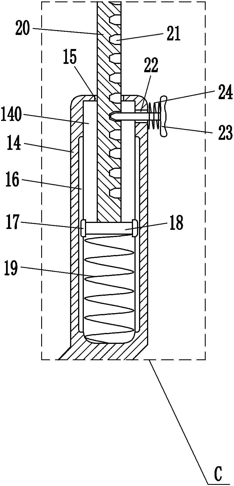
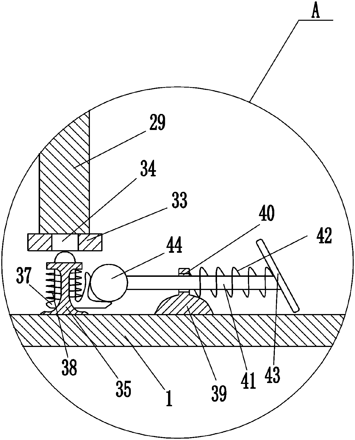
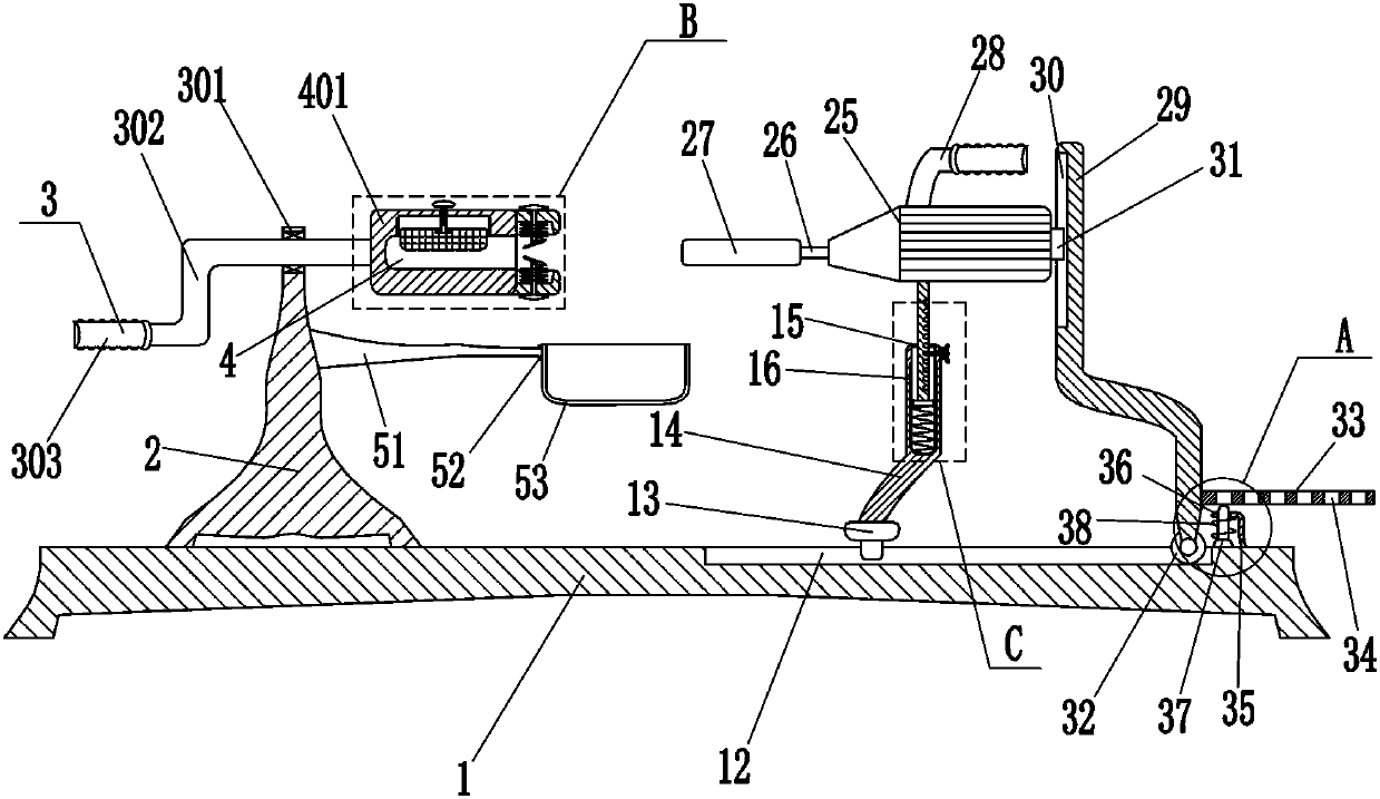
[0017] A tubular hardware grinding device, such as Figure 1-4 As shown, it includes a base 1, a first bracket 2, a rotating device 3, a fixed plate 401, a screw 7, a second bearing seat 8, an extrusion block 9, a first slide rail 10, a first slide block 11, and a second slide Block 13, the second support 14, the third slide rail 16, the third slide block 17, the cross plate 18, the first spring 19, the moving bar 20, the first inserting rod 23, the second spring 24, the motor 25, the rotating shaft 26, Grinding column 27, second handle 28, third support 29, fourth slider 31 and pulley 32, first support 2 is fixedly connected to the left side of the top of base 1, base 1 is connected with first support 2 by means of bolt connection, The first bracket 2 is provided with a rotating device 3, and the rotating device 3 is connected with a fixed plate 401. The right side of the fixed plate 401 has a first groove 4 for placing tubular hardware, and the top of the first groove 4 has ...

Embodiment 2

[0019] A tubular hardware grinding device, such as Figure 1-4As shown, it includes a base 1, a first bracket 2, a rotating device 3, a fixed plate 401, a screw 7, a second bearing seat 8, an extrusion block 9, a first slide rail 10, a first slide block 11, and a second slide Block 13, the second support 14, the third slide rail 16, the third slide block 17, the cross plate 18, the first spring 19, the moving bar 20, the first inserting rod 23, the second spring 24, the motor 25, the rotating shaft 26, Grinding column 27, second handle 28, third support 29, fourth slide block 31 and pulley 32, base 1 top left side is fixedly connected with first support 2, first support 2 is provided with rotating device 3, rotating device 3 A fixed plate 401 is connected to the top, and the right side of the fixed plate 401 is provided with a first groove 4 for placing tubular hardware. The top of the first groove 4 is provided with a second groove 5, and the top of the fixed plate 401 is pro...

Embodiment 3

[0022] A tubular hardware grinding device, such as Figure 1-4 As shown, it includes a base 1, a first bracket 2, a rotating device 3, a fixed plate 401, a screw 7, a second bearing seat 8, an extrusion block 9, a first slide rail 10, a first slide block 11, and a second slide Block 13, the second support 14, the third slide rail 16, the third slide block 17, the cross plate 18, the first spring 19, the moving bar 20, the first inserting rod 23, the second spring 24, the motor 25, the rotating shaft 26, Grinding column 27, second handle 28, third support 29, fourth slide block 31 and pulley 32, base 1 top left side is fixedly connected with first support 2, first support 2 is provided with rotating device 3, rotating device 3 A fixed plate 401 is connected to the top, and the right side of the fixed plate 401 is provided with a first groove 4 for placing tubular hardware. The top of the first groove 4 is provided with a second groove 5, and the top of the fixed plate 401 is pr...


PUM


Abstract

The invention relates to a grinding device, in particular to a tubular hardware grinding device. The tubular hardware grinding device enables people to operate the device more easily and can avoid injuring hands of people. The tubular hardware grinding device comprises a base, a first support, a rotating device, a fixing plate, a screw rod, a second bearing pedestal, a squeezing block, a first sliding rail, a first sliding block, a second sliding block, a second support and the like. The first support is fixedly connected to the left side of the top of the base and provided with the rotating device, the fixing plate is connected to the rotating device, and the right side of the fixing plate is provided with a first groove for placing tubular hardware. Tubular hardware can be ground by rotating a grinding column, so that the workload of people can be alleviated, people can operate the device more easily, people avoid holding the tubular hardware, therefore, hands of people are preventedfrom being injured, a fixing rod can be fixed through a special-shaped clamping block, and therefore stability of a third support can be improved.

Description

technical field [0001] The invention relates to a grinding device, in particular to a grinding device for tubular hardware. Background technique [0002] After the tubular hardware is produced, burrs will remain on the end surface. In order not to affect the use, the tubular hardware needs to be polished. Nowadays, people usually hold the tubular hardware in one hand and a file in the other to polish the tubular hardware. In this way, People's hands are prone to fatigue, and the burrs are relatively sharp, which is easy to hurt people's hands; in order to avoid hurting hands, people wear gloves to polish tubular hardware, which is easy to slip and is inconvenient for people to operate. Contents of the invention [0003] In order to overcome the shortcomings that people hold the tubular hardware in one hand and grind the tubular hardware with a file in the other hand, people's hands are prone to fatigue and hurt their hands, the technical problem of the present invention is...

Claims


Application Information

Patent Timeline
Patent Type & Authority Applications(China)
IPC IPC(8): B24B9/04B24B41/06
CPCB24B9/007B24B9/04B24B41/06
Inventor 欧阳范范
Owner 佛山市迈向成五金件有限公司
Why Eureka
Try Eureka