Multi-angle plate polishing device
A multi-angle, plate technology, used in grinding drives, grinding machines, grinding racks, etc., can solve the problems of harsh working environment, inability to grind the surface of the plate, low production efficiency, etc., to reduce labor intensity of workers and improve grinding. Limitation, the effect of improving production efficiency
- Summary
- Abstract
- Description
- Claims
- Application Information
AI Technical Summary
Problems solved by technology
Method used
Image
Examples
specific Embodiment approach 1
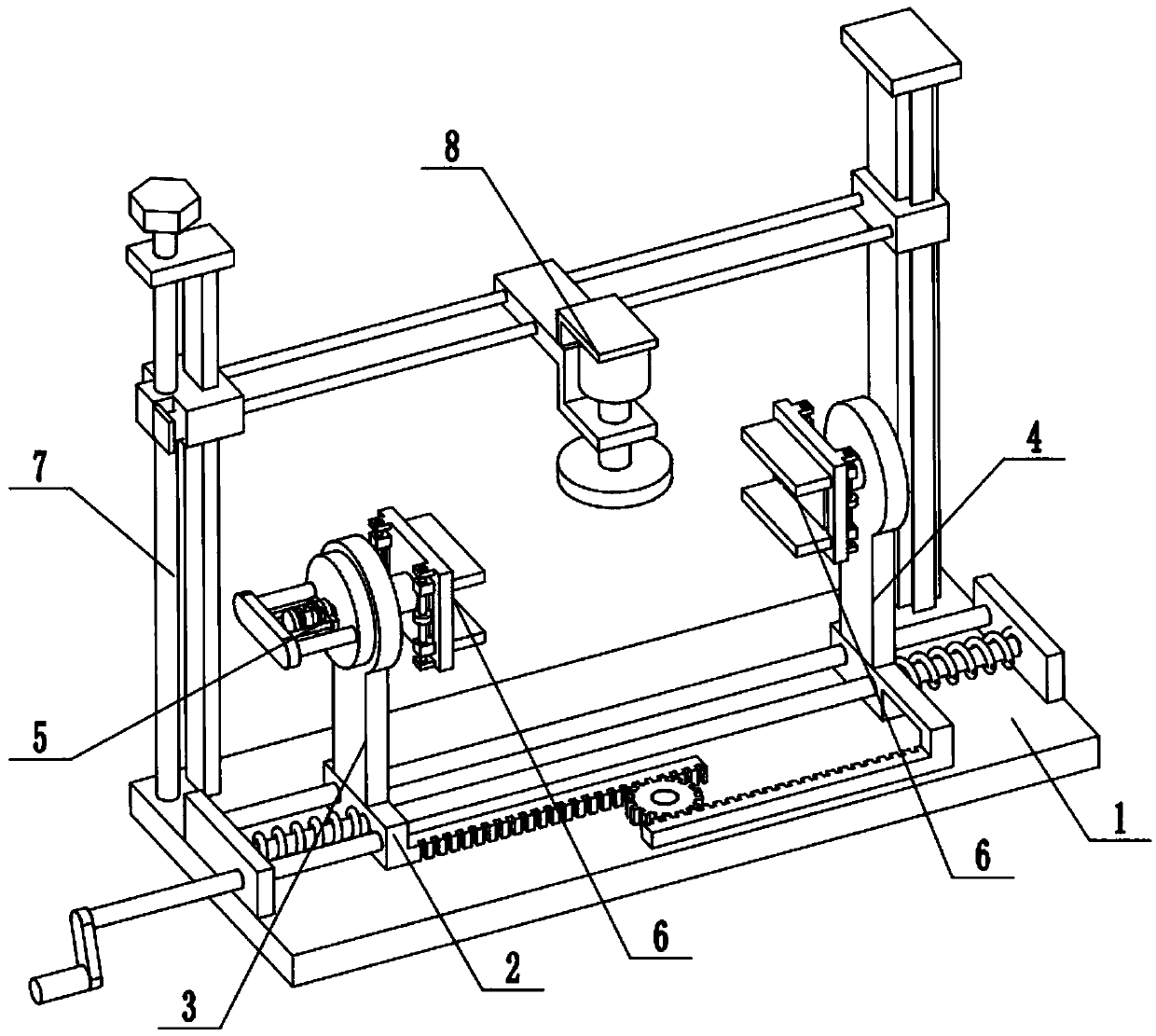
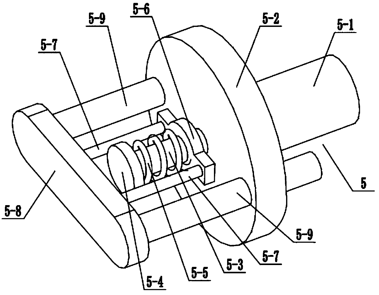
[0022] Combine below Figure 1-5Describe this embodiment, a multi-angle plate grinding device, including a base 1, a length adjustment assembly 2, a left plate 3, a right plate 4, an angle adjustment assembly 5, a plate clamp 6, a grinding disc slide assembly 7 and a grinding assembly 8. The length adjustment assembly 2 is fixedly connected to the front end of the base 1, the left plate 3 and the right plate 4 are respectively fixedly connected to both ends of the length adjustment assembly 2, the angle adjustment assembly 5 is connected to the upper end of the left plate 3, and the plate clip There are two clamping parts 6, and the two plate clamping parts 6 are respectively fixedly connected to the inside of the angle adjustment assembly 5 and the right side plate 4, the grinding disc slide assembly 7 is fixedly connected to the rear end of the base 1, and the grinding assembly 8 is slidably connected to On the grinding disc slide assembly 7 , the grinding assembly 8 is loca...
specific Embodiment approach 2
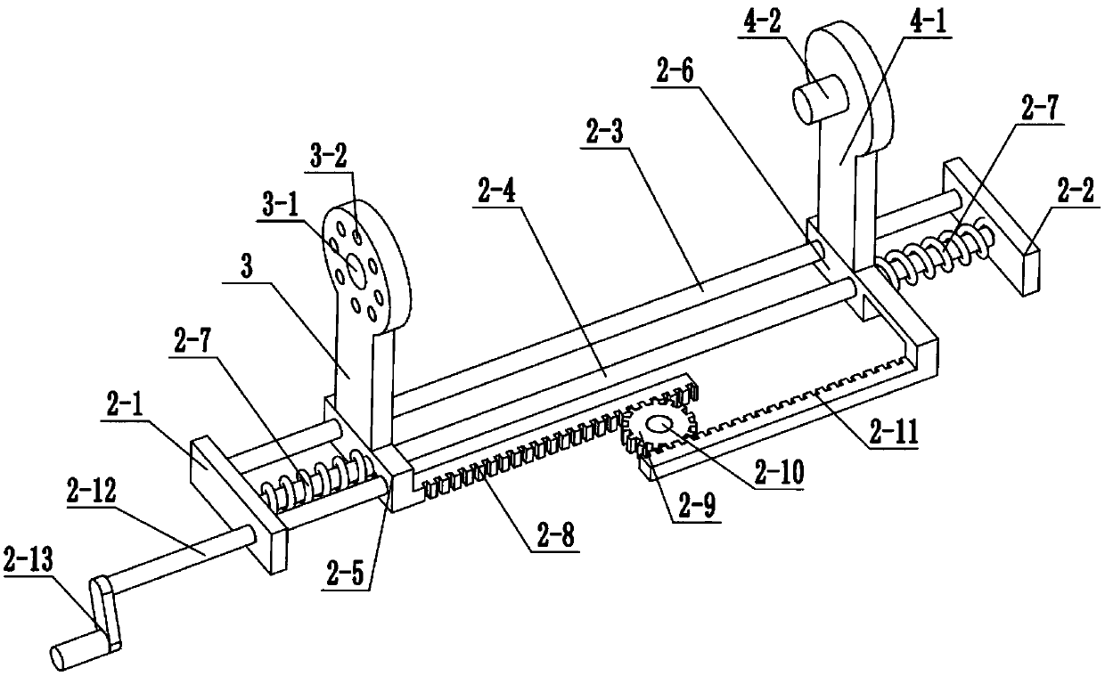
[0023] Combine below Figure 1-5 To illustrate this embodiment, the length adjustment assembly 2 includes a left plate 2-1, a right plate 2-2, a guide rod 2-3, a spring sleeve rod 2-4, a left slide 2-5, a right slide 2- 6. Tension spring 2-7, first rack 2-8, gear 2-9, gear shaft 2-10, second rack 2-11, adjusting screw I 2-12 and hand lever 2-13; left The plate 2-1 and the right plate 2-2 are respectively fixedly connected to the left and right ends of the base 1, and the left plate 2-1 and the right plate 2-2 are fixedly connected to the guide rod 2-3 and the spring sleeve rod 2-4. Sliding seat 2-5 is slidably connected to the left end of guide rod 2-3 and spring sleeve rod 2-4, and right sliding seat 2-6 is slidably connected to the right end of guide rod 2-3 and spring sleeve rod 2-4, and spring sleeve rod 2-4 is sheathed with two tension springs 2-7, and the inner ends of the two tension springs 2-7 are fixedly connected to the left sliding seat 2-5 and the right sliding s...
specific Embodiment approach 3
[0024] Combine below Figure 1-5 To illustrate this embodiment, the left side plate 3 is fixedly connected to the top surface of the left sliding seat 2-5, the upper end of the left side plate 3 is provided with a circular through hole 3-1, and a plurality of jacks 3-2 surround the circle The axis of the through-hole 3-1 is evenly arranged on the left plate 3 around.
PUM
 Abstract
Description
Claims
Application Information
 - R&D
- Intellectual Property
- Life Sciences
- Materials
- Tech Scout
- Unparalleled Data Quality
- Higher Quality Content
- 60% Fewer Hallucinations
Browse by: Latest US Patents, China's latest patents, Technical Efficacy Thesaurus, Application Domain, Technology Topic, Popular Technical Reports.
© 2025 PatSnap. All rights reserved.Legal|Privacy policy|Modern Slavery Act Transparency Statement|Sitemap|About US| Contact US: help@patsnap.com


