Ice surface sliding tool

A tool and ice surface technology, applied in the field of ice gliding tools, can solve the problems of difficult large-scale promotion, poor power output and durability, etc.

Active Publication Date: 2019-04-05
杨松梅
View PDF5 Cites 1 Cited by
  • Summary
  • Abstract
  • Description
  • Claims
  • Application Information

AI Technical Summary

Problems solved by technology

In view of this, the present invention provides a simple structure, reasonable design, can be realized, to at least solve the problems of poor power output and durability, and difficult to promote in a large area

Method used


Image

  • Ice surface sliding tool
  • Ice surface sliding tool
  • Ice surface sliding tool

Examples


specific Embodiment approach 1

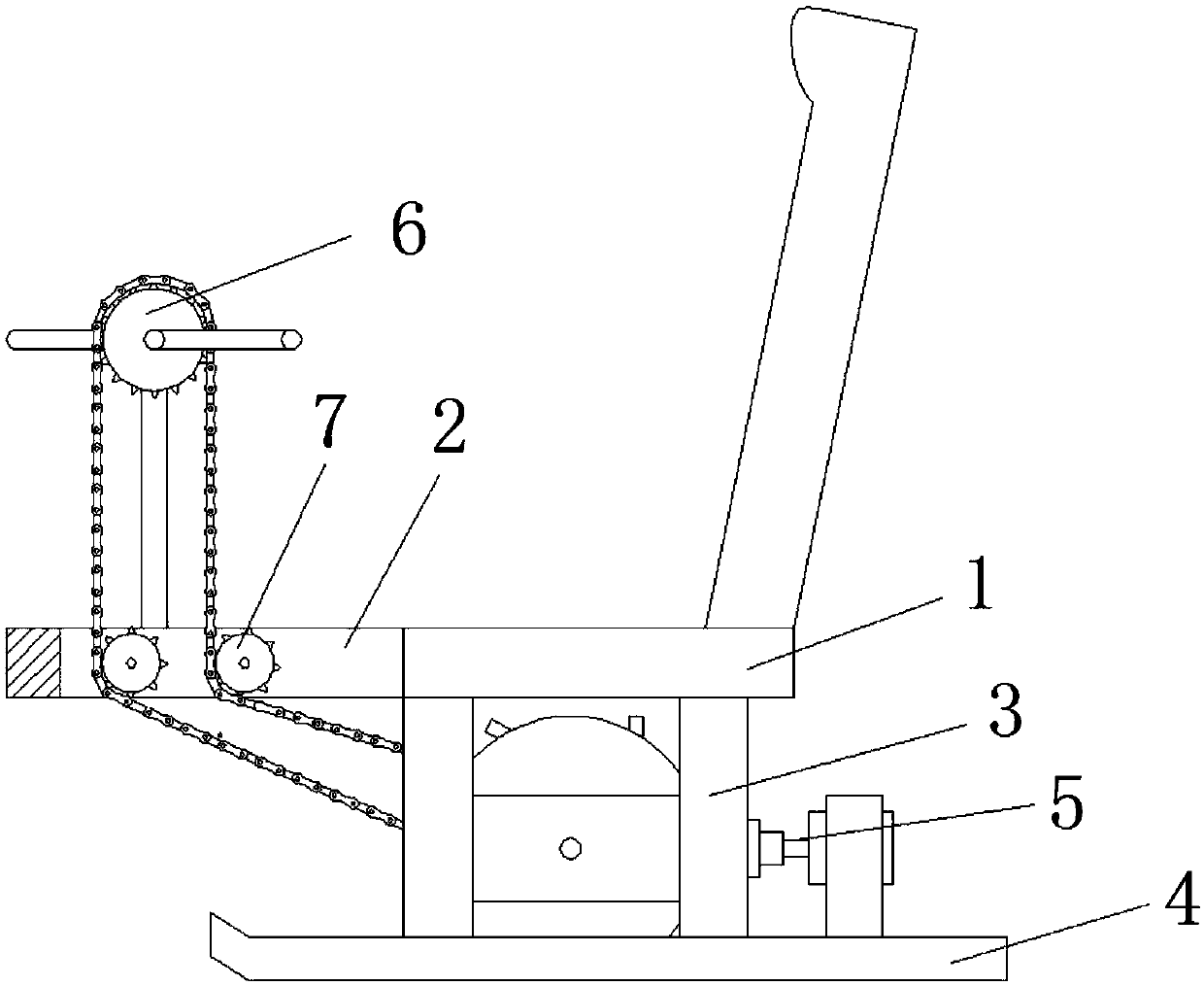
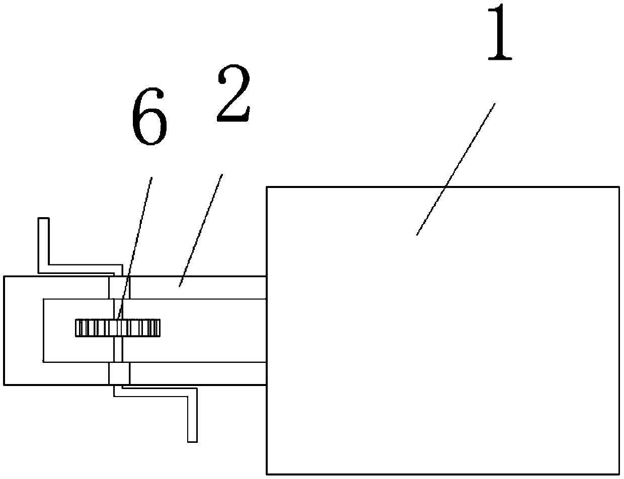
[0051] Such as Figures 1 to 10 As shown, the ice skating tool disclosed in this embodiment includes a seat plate 1, a U-shaped bar 2, an H-shaped connecting frame 3, a skateboard 4, a pushing device 5, a hand crank 6 and a direction-changing gear 7; One end of the upper end surface of the seat plate 1 is provided with a backrest, the other end side wall of the seat plate 1 is provided with a U-shaped rod 2, and the lower end of the seat plate 1 is provided with two slide plates 4 parallel and symmetrically through the H-shaped connecting frame 3, A pushing device 5 is arranged between the two H-shaped connecting frames 3, and the manual chainring 6 is arranged on the upper end of the U-shaped rod 2 through a strut, and the manual cranking plate 6 is connected with the pushing device 5 through a chain , the chain passes through the U-shaped rod 2 and cooperates with the direction-changing gear 7. By manually rotating the manual turntable 6, the pushing device 5 is driven to pr...

specific Embodiment approach 2

[0059] combine Figure 11 , 12 As shown, this embodiment is based on the first embodiment, the difference is that the transmission member 5-3-6 includes a first connecting rod 5-3-6-1, a second connecting rod 5-3-6 -2 and sleeve 5-3-6-3; the two first connecting rods 5-3-6-1 and the two second connecting rods 5-3-6-2 are symmetrically arranged on the first disc Between 5-3-1 and the second disk 5-3-2, one end of the two first connecting rods 5-3-6-1 are respectively arranged on the first disk 5-3-1 and On the inner side wall of the second disc 5-3-2, the other end of the first connecting rod 5-3-6-1 passes through the second connecting rod 5-3-6-2 and the casing 5-3-6-3 Connected, the casing 5-3-6-3 is connected with the friction member 5-3-7 through a hinged seat;

[0060] When the second disc 5-3-2 moves away from the first disc 5-3-1, the second disc 5-3-2 pulls the first connecting rod 5-3-6-1 through the hinged seat, Make the angle between the two first connecting rod...

specific Embodiment approach 3

[0062] combine Figure 4 , 6 , 13, and 14, this embodiment is based on the first specific embodiment, the difference is that the friction member 5-3-7 includes a slat 5-3-7-1, a limit bar 5-3- 7-2. U-shaped frame 5-3-7-3 and second pressure spring 5-3-7-5; the rod shaft is provided with slat 5-3-7-1 and limit bar 5- 3-7-2, the two ends of the slat 5-3-7-1 are symmetrically provided with limit strips 5-3-7-2, and the rear side wall of the slat 5-3-7-1 passes through the hinged seat and the casing 5-3-6-3 is connected, and the U-shaped frame 5-3-7-3 is movably arranged between the first circular disk 5-3-1 and the second circular disk 5-3-2, and the U-shaped frame 5- Both vertical side walls of 3-7-3 are provided with a strip-shaped cavity 5-3-7-4, and the limiting strip 5-3-7-2 is movably arranged in the strip-shaped cavity 5-3-7-4 , the front side wall of the slat 5-3-7-1 is connected with the bottom inner wall of the U-shaped frame 5-3-7-3 through the second pressure sprin...


PUM


Abstract

The invention provides an ice surface sliding tool and belongs to the technical field of sliding tools. The ice surface sliding tool aims at solving the problems that power output and durability are poor, and large-scale popularization is difficult. The ice surface sliding tool comprises a seat board, a U-shaped rod, H-shaped connecting frames, sliding boards, a pushing device, a hand-rocking chain wheel and turning gears. A backrest is arranged at one end of the upper end face of the seat board, the U-shaped rod is arranged on the side wall at the other end of the seat board, the two slidingboards are symmetrically arranged in parallel at the lower end of the seat board through the H-shaped connecting frames, the pushing device is arranged between the two H-shaped connecting frames, andthe hand-rocking chain wheel is arranged at the upper end of the U-shaped rod through a strut. The problems that power output and durability are poor, and large-scale popularization is difficult are solved, so that the effects that power output is continuously effective, meanwhile, the resistance of the sliding tool in the sliding stage can be reduced, the sliding distance is long, durability is strong, and popularization is easy are achieved.

Description

technical field [0001] The invention belongs to the technical field of gliding tools, and in particular relates to gliding tools on ice surfaces. Background technique [0002] In winter in the north, there is a world of ice and snow everywhere. Ice and snow are a unique wealth for northerners. Northerners love ice and snow, and have created a unique ice and snow culture by looking at ice and snow resources from a cultural perspective. It is possible to make full use of ice and snow and vigorously develop ice and snow tourism culture. How to make tourists better enjoy the enjoyment brought by the world of ice and snow is a key issue. Ice gliding tools can allow tourists to quickly enjoy the fun of ice gliding. Feel the charm of ice and snow. Existing gliding tools, such as ice sledges, need to be pierced on the ice with a sharp iron rod at one end to push the ice sledge to slide forward. It requires certain skills and is dangerous, and the power is poor. The distance is sho...

Claims


Application Information

Patent Timeline
IPC IPC(8): B62B13/00B62B17/00
CPCB62B13/00B62B17/00
Inventor 宋文利李智鹏张萍杨蕊竹宁博文于阳洋张宇新韩冰
Owner 杨松梅
Why Eureka
Try Eureka