Method and device for terminating uplink continuous repeated transmission, base station and user equipment

A technology for repeated transmission and user equipment, which is applied in transmission systems, digital transmission systems, and error prevention. The effect of saving user transmission resources

Active Publication Date: 2019-04-05
BEIJING SPREADTRUM HI TECH COMM TECH CO LTD
View PDF5 Cites 3 Cited by
  • Summary
  • Abstract
  • Description
  • Claims
  • Application Information

AI Technical Summary

Problems solved by technology

[0006] For the uplink K times continuous repeated transmission method with multiple termination conditions, there is currently no solution to how to configure the monitoring period for multiple termination conditions. Users cannot use multiple termination conditions to terminate subsequent repeated transmissions in time, resulting in waste of user resources.

Method used


Image

  • Method and device for terminating uplink continuous repeated transmission, base station and user equipment
  • Method and device for terminating uplink continuous repeated transmission, base station and user equipment
  • Method and device for terminating uplink continuous repeated transmission, base station and user equipment

Examples


Embodiment 1

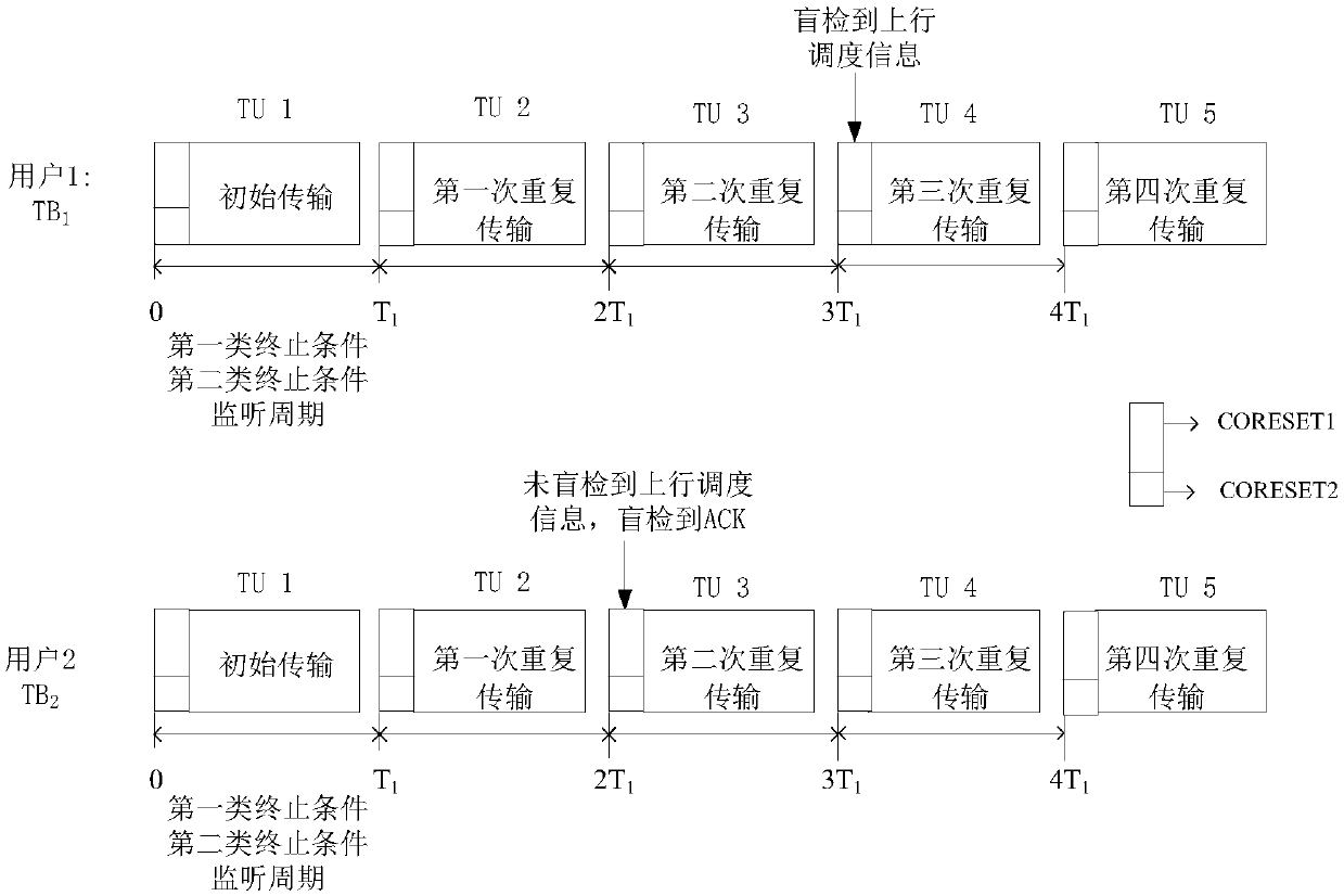
[0073] Such as image 3As shown, X=1, that is, the two types of termination conditions have the same monitoring period, and the length is T1. The set of control resources for transmitting the first type of termination condition is CORESET1, and the set of control resources for transmitting the second type of termination condition is CORESET2. In this embodiment, user 1 and user 2 have the same control resource sets CORESET1 and CORESET2. The base station sends the configuration information of CORESET1 to user 1 and user 2 including the listening period T1 of the first type of termination condition, and the base station sends the configuration information of CORESET2 to user 1 and user 2 including the monitoring period T1 of the second type of termination condition. User 1 and user 2 respectively start to perform K consecutive repeated transmissions on TB1 and TB2 in time unit (Time Unit, TU) 1, K=5. In this embodiment, the first type of termination condition is the uplink sc...

Embodiment 2

[0077] Such as Figure 4 As shown, X=2, that is, the monitoring period of the first type of termination condition is twice that of the second type of termination condition, and the lengths are 2T1 and T1 respectively. The set of control resources for transmitting the first type of termination condition is CORESET1, and the set of control resources for transmitting the second type of termination condition is CORESET2. In this embodiment, user 1 and user 2 have the same control resource sets CORESET1 and CORESET2. The base station sends the configuration information of CORESET1 to user 1 and user 2 including the listening period 2T1 of the first type of termination condition, and the base station sends the configuration information of CORESET2 to user 1 and user 2 including the monitoring period of the second type of termination condition T1. User 1 and user 2 respectively start to perform K consecutive repeated transmissions to TB1 and TB2 in TU1, K=5. In this embodiment, the...


PUM


Abstract

The invention provides a method and a device for terminating uplink continuous repeated transmission, a base station and a piece of user equipment. The method includes the following steps: receiving the monitoring period of a first type of termination conditions and the monitoring period of a second type of termination conditions configured by a base station during uplink continuous repeated transmission of the same transmission block, wherein the monitoring period length of the first type of termination conditions is X times of the monitoring period length of the second type of termination conditions, and X is an integer greater than or equal to 1; carrying out blind test on the two types of termination conditions according to the monitoring period of the first type of termination conditions and the monitoring period of the second type of termination conditions; and choosing whether or not to terminate the uplink continuous repeated transmission of the transmission block according tothe blind test result. Subsequent repeated transmission can be terminated in time according to the termination conditions, so that the transmission resources of users can be saved, and the complexityof blind test by users can be reduced.

Description

technical field [0001] The present invention relates to the technical field of wireless communication, in particular to a method, device, base station and user equipment for terminating uplink continuous and repeated transmission. Background technique [0002] For the URLLC (Ultra Reliable Low Latency Communication) service in 5G, 3GPP (3rd Generation Partnership Project, 3rd Generation Partnership Project) reached an agreement after discussion, and URLLC users support scheduling-based (with grant) There are two types of uplink transmissions and no-scheduling (without grant), and for these two types, a total of K times of repeated transmissions including the initial transmission for the same TB (Transport Block, transport block) are supported. [0003] 3GPP also discussed the termination conditions when URLLC performs K transmissions and adopted the following conclusions: the user performs repeated transmissions on the same TB until the uplink scheduling (UL grant) for the T...

Claims


Application Information

Patent Timeline
Patent Type & Authority Applications(China)
IPC IPC(8): H04L1/18H04L1/16
CPCH04L1/1607H04L1/1812
Inventor 曲鑫
Owner BEIJING SPREADTRUM HI TECH COMM TECH CO LTD
Why Eureka
Try Eureka