Automatic torsion spring assembling machine for illuminating lamp production

A technology for lighting lamps and assembling machines, applied in manufacturing tools, metal processing, metal processing equipment, etc., can solve the problems of inability to meet the development trend of high efficiency, high quality and low cost, laborious manual operation, and high labor costs. High assembly quality, reduced labor costs, and labor-saving effects

Pending Publication Date: 2019-04-09
广东大唐永恒智能科技有限公司
0 Cites 6 Cited by

AI-Extracted Technical Summary

Problems solved by technology

[0004] At present, in the production process of downlights and ceiling lamps, the torsion springs on both sides of the downlights or ceiling lamps are manually assembled, first installing the torsion spring on one side and then installing the torsion spring on the other side. The output and quality largely depend o...

Method used

[0038] The lamp conveying mechanism 3 of the present embodiment includes a conveyor belt driving mechanism 31, a conveyor belt 32 and a fixture 33. The conveyor belt 32 is erected on the frame 1 through the rotating shafts at both ends, and the conveyor belt driving mechanism 31 is in transmission connection with the rotating shaft at one end. The conveyor driving mechanism 31 includes a sixth driving member 311 , a speed reducer 312 and an encoder 313 . The sixth driving element 311 is installed on the frame 1 and located below the conveyor belt 32 , and the sixth driving element 311 in this embodiment is a servo motor. The speed reducer 312 is installed on the frame and the output shaft of the speed reducer 312 is connected with the rotating shaft at the tail end of the conveyor belt 32 through a coupling. The sixth driving member 311 is connected to the speed reducer 312 through a belt drive. The encoder 313 is connected with the reducer 312 and is used to control the reducer 312 . Therefore, the cooperation of the servo driver and the reducer 312 can realize the driving of the conveyor belt 32 and complete the transportation of the lamps 6; the setting of the encoder 313 can correct the position of the conveyor belt 32 in time to ensure safe and continuous production . The lamp 6 is fixedly installed in the fixture 33 . There are multiple tooling fixtures 33 in this embodiment, and the multiple tooling fixtures 33 are arranged and installed on the conveyor belt 32 in sequence. Each lamp 6 is fixed on the fixture 33, and multiple fixtures 33 are arranged and installed on the conveyor belt 32 in sequence. Under the action of the conveyor belt 32, the flow operation of the assembly of the lamp 6 is realized, and then the assembly and production of the torsion spring 7 is realized. Fully automated and continuous.
[0042] As shown in FIGS. 1 and 2, the lamp position correction device 88 is installed on the frame 1 and located at the head end of the conveyor belt 32. As shown in FIG. 5 , the lamp position correcting device 8 of this embodiment includes a third clip arm 81 and a tenth driving member 82 . The third clip arm 81 cooperates with the lug 61 of the lamp, and is used for clamping the lug 61 on one side of the lamp. The tenth driving member 82 in this embodiment is a telescopic cylinder. The telescopic end of the tenth driving member 82 is connected with the third clip arm 81 for driving the third clip arm 81 to open or close. Therefore, the lamp position correcting device 8 is arranged at the input end of the lamp conveying device 3, and is used for correcting the positi...

Abstract

The invention discloses an automatic torsion spring assembling machine for illuminating lamp production. The automatic torsion spring assembling machine for the illuminating lamp production comprisesa machine frame, torsion spring feeding devices, a lamp conveying device, torsion spring conveying devices and torsion spring mounting devices, wherein the torsion spring feeding devices, the lamp conveying device, the torsion spring conveying devices and the torsion spring mounting devices are arranged on the machine frame, the torsion spring conveying devices are matched with the torsion springfeeding devices and the torsion spring mounting devices, the torsion spring conveying devices are arranged for conveying torsion springs from the torsion spring feeding devices to the torsion spring mounting devices, and the torsion spring mounting devices are arranged for mounting the torsion springs on lamps conveyed by the lamp conveying device. Therefore, the automatic torsion spring assembling machine can automatically carry out the processes from feeding to mounting, the production efficiency is high, the assembling quality is high, the manual operation is almost not needed in the wholeproduction process, and a large amount of labor is thus saved so as to greatly reduce the labor cost.

Application Domain

Technology Topic

Image

  • Automatic torsion spring assembling machine for illuminating lamp production
  • Automatic torsion spring assembling machine for illuminating lamp production
  • Automatic torsion spring assembling machine for illuminating lamp production

Examples

  • Experimental program(1)

Example Embodiment

[0033] The present invention will be further described in detail below in conjunction with the drawings.
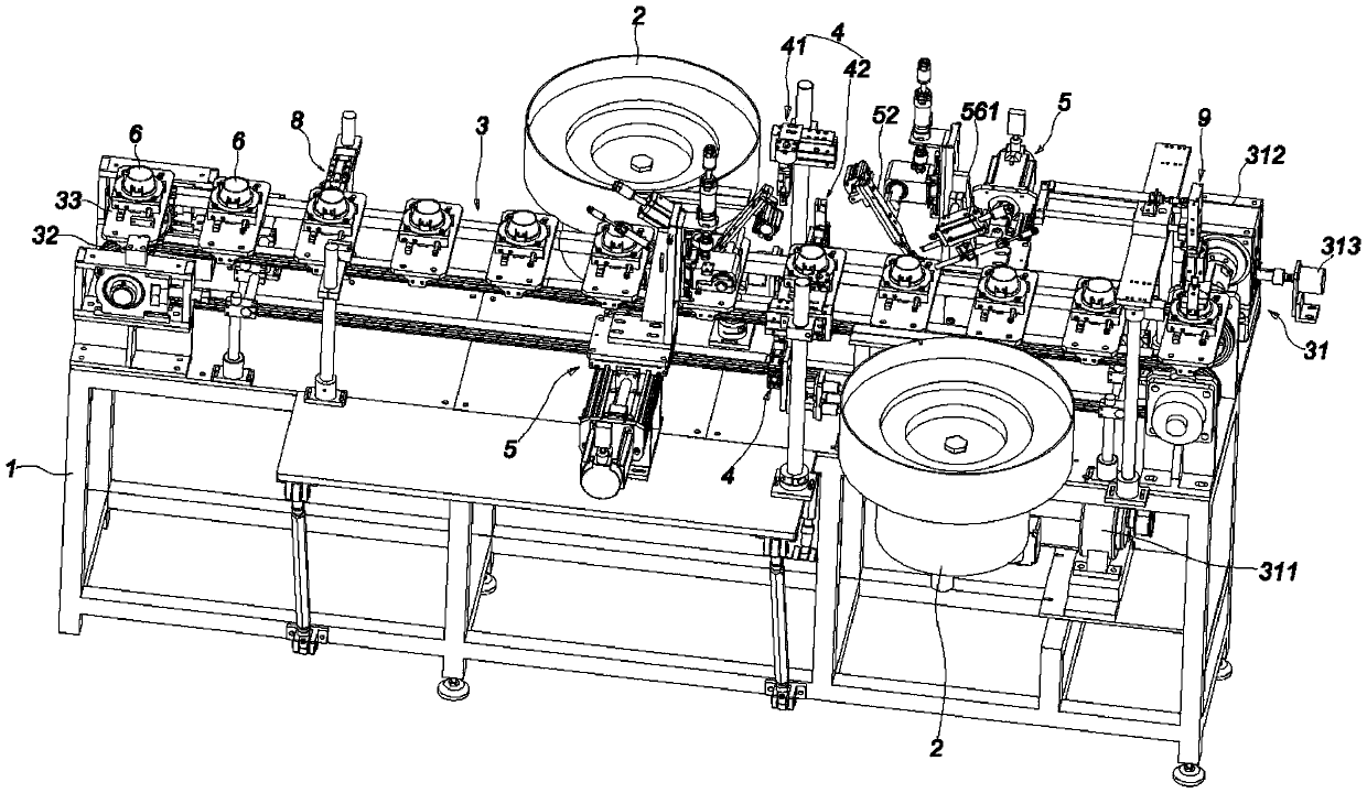
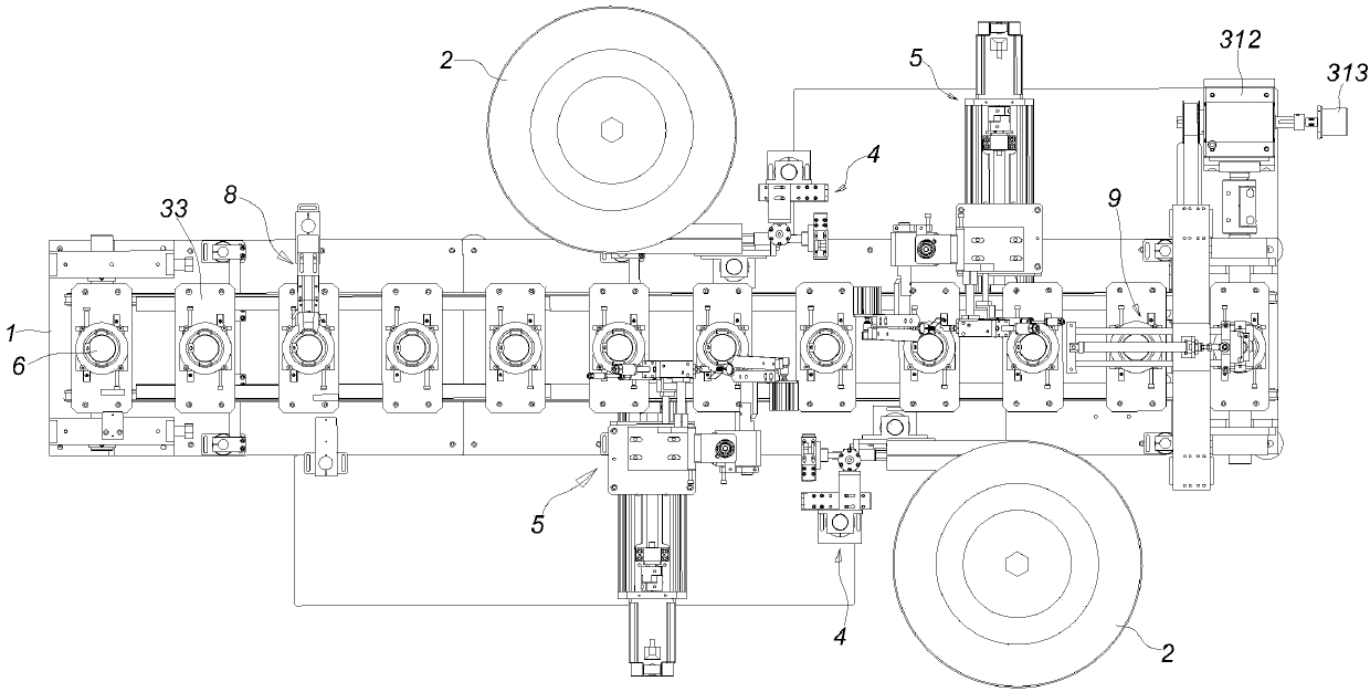
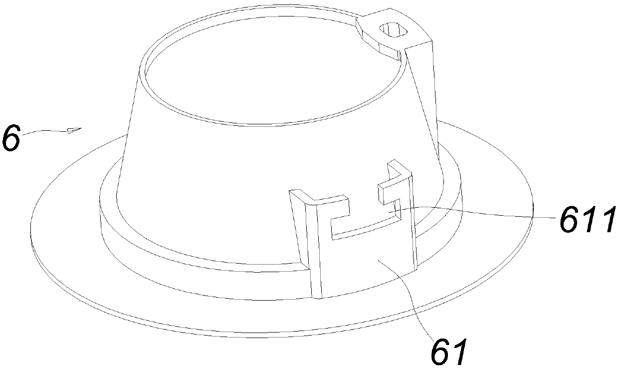
[0034] Figure 1~13 It schematically shows an automatic torsion spring assembly machine for the production of lighting lamps according to an embodiment of the present invention.
[0035] Such as Figure 1~13 As shown, the automatic torsion spring assembly machine for the production of lighting lamps includes a frame 1, a torsion spring feeding device 2, a lamp conveying device 3, a torsion spring conveying device 4, a torsion spring installation mechanism 5, a lamp position correction device 8 and a lamp outlet 料装置9。 Material device 9. The torsion spring installation device 5, the torsion spring feeding device 2, the lamp conveying device 3 and the torsion spring conveying device 4 are all installed in the frame 1. The torsion spring conveying device 4 cooperates with the torsion spring feeding device 2 and the torsion spring mounting device 5 respectively. The torsion spring conveying device 4 is used for conveying the torsion spring 7 from the torsion spring feeding device 2 to the torsion spring mounting device 5. The spring installation device 5 is used to install the torsion spring 7 on the lamp 6 conveyed from the lamp conveying device 3.
[0036] Such as Figure 5 As shown, the torsion spring 7 of this embodiment is a common type of spring on the market. The upper end of the torsion spring 7 has a spiral cylindrical structure, and one end of the torsion spring 7 is provided with a torsion spring end 71.
[0037] Such as Figure 4 As shown, the lamp 6 in this embodiment may be a downlight or a ceiling lamp commonly available in the market. Lugs 61 are provided on both sides of the lamp 6. Each lug is provided with a torsion spring installation groove 611 for installing the torsion spring 7.
[0038] The lamp conveying mechanism 3 of this embodiment includes a conveying belt driving mechanism 31, a conveying belt 32 and a fixture 33. The conveyor belt 32 is erected on the frame 1 through the rotating shafts at both ends, and the conveyor belt driving mechanism 31 is drivingly connected with the rotating shaft at one end. The conveyor belt driving mechanism 31 includes a sixth driving member 311, a speed reducer 312 and an encoder 313. The sixth driving member 311 is installed on the frame 1 and located below the conveyor belt 32. The sixth driving member 311 in this embodiment is a servo motor. The reducer 312 is installed on the frame and the output shaft of the reducer 312 is connected with the rotating shaft at the end of the conveyor belt 32 through a coupling. The sixth driving member 311 and the reducer 312 are connected by a belt drive. The encoder 313 is connected to the reducer 312 and is used to control the reducer 312. Therefore, the cooperation of the servo drive and the reducer 312 can drive the conveyor belt 32 and complete the transportation of the lamp 6; the encoder 313 can correct the position of the conveyor belt 32 in time to ensure safe and continuous production . The lamp 6 is fixedly installed in the fixture 33. There are a plurality of tooling jigs 33 in this embodiment, and the plurality of tooling jigs 33 are sequentially installed on the conveyor belt 32 in a row. Each lamp 6 is fixed on the fixture 33, and a plurality of fixtures 33 are arranged in sequence and installed on the conveyor belt 32. Under the action of the conveyor belt 32, the assembly line of the lamps 6 is realized, and the assembly production of the torsion spring 7 is realized. Fully automated and continuous.
[0039] Such as Figure 5 with 6 As shown, the tooling fixture 33 of this embodiment includes a limiting member 331, a second mounting frame 332, a mounting bottom plate 333, a linkage rod 334, a fourth guide rail 335, a fourth sliding block 336, and a ninth driving member 337. Both sides of the mounting bottom plate 333 are fixedly mounted to the conveyor belt 32 by pins or screws. The fourth guide rail 335 is fixedly installed above the mounting base plate 333 by screws or the like. The fourth sliding block 336 is sleeved on the outer circumference of the fourth guide rail 335 and slidably fits with the fourth guide rail 335. The second mounting bracket 332 is slidably mounted above the mounting bottom plate 333. The ninth driving member 337 of this embodiment is a telescopic cylinder. The telescopic end of the ninth driving member 337 is fixedly connected to the fourth sliding block 336. The second mounting frame 332, the fourth sliding block 336, and the fourth guide rail 335 of this embodiment are all two groups, that is, the second mounting frame 332, the fourth sliding block 336 and the fourth guide rail 335 are all two. Two sets of second mounting brackets 332 and two sets of fourth guide rails 335 are vertically arranged, and two second mounting brackets 332 and two fourth guide rails 335 enclose a square. The middle part of the linkage rod 334 is pin-connected to the mounting bottom plate 333, and the two ends of the linkage rod 334 are respectively mounted on the two fourth sliding blocks 336. The limiting member 331 is fixedly installed on the second mounting frame 332, and the limiting member 331 is matched with the edge of the lamp. There are four limiting members 331 in this embodiment, and the limiting members 331 may be bolts. The four limiting members 331 are respectively located at the four corners of the two second mounting frames 332. Therefore, the tooling fixture 33 of this embodiment is an adjustable fixture, which can be adjusted according to the size of the lamp 6 to meet different production requirements and has strong applicability.
[0040] The working principle of the fixture 33 is: the ninth driving member 337 extends and pushes one of the fourth sliding blocks 336 connected to it to slide on the fourth guide rail 335, and drives the second installation fixedly connected to the fourth sliding block 336 The frame 332 moves outwards, while the fourth slider 336 slides to drive one end of the linkage rod 334 to move together, and the other end of the linkage rod 334 pushes another fourth slider 336 to move in the opposite direction along the other fourth guide rail 335 , Driving the second mounting frame 332 fixedly connected to the fourth sliding block 336 to move outwards, and the distance between the limiting members 331 of the two second mounting frames 332 becomes larger; on the contrary, the ninth driving member 337 shrinks and pulls One of the fourth sliding blocks 336 connected to the fourth sliding block 336 slides on the fourth guide rail 335 to drive the second mounting frame 332 fixedly connected to the fourth sliding block 336 to move inward, while the fourth sliding block 336 slides to drive the linkage rod 334 One end moves together, and the other end of the linkage rod 334 pushes the other fourth slider 336 to move in the opposite direction along the other fourth rail 335, driving the second mounting frame 332 fixedly connected to the fourth slider 336 to Inward movement, the distance between the stoppers 331 of the two second mounting brackets 332 becomes smaller. To put it simply: the ninth driving member 337 is extended to drive the two second mounting brackets 332 to expand outward at the same time, and the distance between the limit members 331 becomes larger, which is convenient for the removal and installation of the lamp 6 or is suitable for larger models Lamp; On the contrary, the ninth driving member 337 is contracted, driving the two second mounting frames 332 to recycle inward at the same time, and the distance between the limiting members 331 becomes smaller, and the lamp 6 is fixed.
[0041] In this embodiment, the lamp 6 can be placed on the first fixture 33 automatically or manually by a manipulator.
[0042] Such as figure 1 with 2 As shown, the lamp position correction device 88 is installed on the frame 1 and located at the head end of the conveyor belt 32. Such as Figure 5 As shown, the lamp position correction device 8 of this embodiment includes a third clamping arm 81 and a tenth driving member 82. The third clamping arm 81 cooperates with the lug 61 of the lamp, and is used to clamp the lug 61 on one side of the lamp. The tenth driving member 82 of this embodiment is a telescopic cylinder. The telescopic end of the tenth driving member 82 is connected with the third clamping arm 81 for driving the third clamping arm 81 to open or close. Therefore, the lamp position correction device 8 is arranged at the input end of the lamp conveying device 3, and is used to correct the position of the lamp 6 to be torsion spring installed, so as to ensure that the direction of each lamp 6 is consistent (the lugs on both sides of the lamp 61 towards the outside) thereby greatly improving assembly efficiency and assembly quality. The working principle of the lamp position correction device 8 of this embodiment is: when the lamp 6 is conveyed to the position of the lamp position correction device 8 under the action of the lamp conveying device 3, the tenth driving member 82 drives the third clamp arm 81 to close, The third clamping arm 81 clamps the lug 61 on one side of the lamp to complete the correction of the position of the lamp 6.
[0043] Such as figure 1 with Figure 7 As shown, the torsion spring conveying mechanism 4 of this embodiment is provided behind the torsion spring feeding mechanism 2. The torsion spring feeding mechanism 2 of this embodiment is a vibrating plate. The torsion spring feeding mechanism 2 is provided with a discharging groove 21 at one end close to the conveyor belt, and the torsion spring 7 is output from the discharging groove 21 under the action of a vibrating disk.
[0044] Such as Figure 8 with 9 As shown, the torsion spring conveying mechanism 4 of this embodiment includes a first clamping and conveying mechanism 41 and a second clamping and conveying mechanism 42. The first clamping and conveying mechanism 41 includes a second torsion spring clamping mechanism 411, a rotation adjustment mechanism 412 and a first horizontal feed X-axis mechanism 413. The second torsion spring clamping mechanism 411 is installed on the rotation adjustment mechanism 412 and used for clamping the torsion spring 7 output from the torsion spring feeding mechanism 2. The second torsion spring clamping mechanism 411 includes a second clamping arm 4111 and a seventh driving member 4112, and the second clamping arm 4111 is installed at the lower end of the seventh driving member 4112. The seventh driving member 4112 is an air cylinder for driving the second clamping arm 4111 to open or close. The rotation adjustment mechanism 412 is slidably mounted on the first horizontal feed X-axis mechanism 413 and is used to drive the second torsion spring clamping mechanism 411 to rotate. The rotation adjustment mechanism 412 in this embodiment is a servo motor, and the lower end of the output shaft of the rotation adjustment mechanism 412 is fixedly connected to the seventh driving member 4112.
[0045] The first horizontal feeding X-axis mechanism 413 is installed on the frame 1, and the first horizontal feeding X-axis mechanism 413 of this embodiment includes an eighth driving member 4131, a third sliding block 4132 and a third guide rail 4133. The eighth driving member 4131 in this embodiment is an air cylinder, and the telescopic rod of the eighth driving member 4131 is fixedly connected to the third sliding block 4132. The third sliding block 4132 is fixedly installed on the frame 1 through a fixing rod, and the rotation adjustment mechanism 412 is fixedly connected to the third sliding block 4132. The third guide rail 4133 is installed in the sliding groove of the outer wall of the eighth driving member 4131, and the lower end of the third sliding block 4132 is fixedly sleeved on the outer periphery of the third guide rail 4133. Thus, driven by the eighth driving member 4131, the third sliding block 4132 drives the rotation adjustment mechanism 412 and the second torsion spring clamping mechanism 411 to slide horizontally along the sliding groove of the outer wall of the eighth driving member 4131 to complete the torsion spring 7 transportation.
[0046] The second clamping and conveying mechanism 42 includes a third torsion spring clamping mechanism 421, a second forward and backward feeding Y-axis mechanism 422, and a second horizontal feeding X-axis mechanism 423. The third torsion spring clamping mechanism 421 is a fixed clamping arm structure, and the upper end of the clamping arm is provided with a mounting groove matching the spiral cylindrical part of the torsion spring 7. The third torsion spring clamping mechanism 421 is slidably mounted on the second forward and backward feeding Y-axis mechanism 422 and is used for placing the torsion spring 7 clamped from the first clamping and conveying mechanism 41. The second front and rear feeding Y-axis mechanism 422 is installed on the second horizontal feeding X-axis mechanism 423, and the second horizontal feeding X-axis mechanism 423 is installed on the frame 1. The structure of the second forward and backward feeding Y-axis mechanism 422 of this embodiment is the same as that of the first horizontal feeding X-axis mechanism 413. The second forward and backward feeding Y-axis mechanism 422 can drive the upper third torsion spring clamping mechanism 421 to move forward and backward. . The second horizontal feed X-axis mechanism 423 is a telescopic cylinder, and the telescopic rod of the telescopic cylinder is fixedly connected to the cylinder of the second front-rear feed Y-axis mechanism 422. The second horizontal feeding X-axis mechanism 423 can drive the second front-rear feeding Y-axis mechanism 422 and the third torsion spring clamping mechanism 421 to move horizontally together. Thus, the second torsion spring clamping mechanism 411 is used to clamp the torsion spring output from the torsion spring feeding mechanism 2 and transport it to the second clamping and conveying mechanism 42 under the action of the first horizontal feed X-axis mechanism 413, The rotation adjustment mechanism 412 is used to drive the second torsion spring clamping mechanism 411 to rotate; the third torsion spring clamping mechanism 421 is used to place the torsion spring 7 clamped from the first clamping and conveying mechanism 41, and move forward and backward in the second Driven by the Y-axis mechanism 422 and the second horizontal feed X-axis mechanism 423, the torsion spring is delivered to the torsion spring installation mechanism 5, and the torsion spring installation mechanism 5 clamps the torsion spring 7 from the third torsion spring clamping mechanism 421 And complete the installation. The entire conveying process is closely coordinated to jointly complete the transportation and loading of the torsion spring 7, and ultimately ensure the efficiency of assembly.
[0047] The torsion spring conveying mechanism 4 of this embodiment further includes a torsion spring position detection mechanism, which is fixedly installed on the outer wall of the seventh driving member 4112 of the second torsion spring clamping mechanism 411. The torsion spring position detection mechanism in this embodiment is a laser sensor for detecting the position of the torsion spring 7 clamped by the second torsion spring clamping mechanism 411, and the torsion spring position detection mechanism cooperates with the rotation adjustment mechanism 412. Therefore, in order to facilitate installation, the torsion spring conveying mechanism 4 of this embodiment needs to ensure that the direction of the torsion spring 7 is consistent (that is, the torsion spring end 71 must face inward toward the torsion spring installation groove 61 of the lamp), and the torsion spring position detection mechanism Used to detect the position of the torsion spring 7 clamped by the second torsion spring clamping mechanism 411. When the position of the torsion spring 7 is wrong, such as the torsion spring end 71 facing away from the lamp, the rotation adjusting mechanism 412 will drive the second torsion spring clamping The mechanism 411 performs rotation adjustment so that the torsion spring end 71 faces the lamp, completing the adjustment of the position of the torsion spring 7.
[0048] Such as Figure 10-12 As shown, the torsion spring installation mechanism 5 of this embodiment includes a mounting frame 51, a first torsion spring clamping mechanism 52, an angle adjustment mechanism 53, a first forward and backward feeding Y-axis mechanism 54, a height adjustment Z-axis mechanism 55, and a torsion spring Promotion agency 56. The first torsion spring clamping mechanism 52 is installed on the angle adjustment mechanism 53 and used for clamping the torsion spring. The angle adjusting mechanism 53 is slidably mounted on the mounting frame 51 and used to drive the first torsion spring clamping mechanism 52 to rotate. The height adjustment Z-axis mechanism 55 is mounted on the mounting frame 51 and one end is connected with the angle adjustment mechanism 53. The mounting frame 51 is slidably mounted on the first forward and backward feeding Y-axis mechanism 54. The torsion spring pushing mechanism 56 is obliquely installed on the mounting frame 51 and cooperates with the first torsion spring clamping mechanism 52.
[0049] Such as Picture 10 As shown, the angle adjustment mechanism 53 of this embodiment is a servo motor. The first torsion spring clamping mechanism 52 includes a first driving member 521 and a first clamping arm 522. There are two first clamping arms 522, and the two first clamping arms 522 are hinged to each other. A first clamping arm 522 at the upper end is fixedly connected to the output shaft of the angle adjustment mechanism 53. The first driving member 521 is installed at one end of the first clamping arm 522 for driving the two first clamping arms 522 to open or close. The first driving member 521 is an air cylinder. Thus, the two first clamping arms 522 are opened or closed by the driving of the first driving member 521, thereby realizing the clamping of the torsion spring 7 and completing the corresponding installation action.
[0050] The height adjustment Z-axis mechanism 55 includes a second driving member 551, a first guide rail 552 and a first sliding block 553. The angle adjustment mechanism 53 is fixedly connected to one end of the first sliding block 553, and the first guide rail 552 is fixedly installed on the mounting frame 51. The other end of the first sliding block 553 is sleeved on the first guide rail 552 and slidably fits with the first guide rail 552. The second driving member 551 is fixedly installed on the mounting frame 51 and the lower end is fixedly connected with the angle adjusting mechanism 53. The second driving member 551 is used to drive the angle adjusting mechanism 53 to slide along the first guide rail 552. The second driving member 551 in this embodiment is an air cylinder. As a result, the second driving member 551 telescopically can drive the angle adjusting mechanism 53 to slide up and down along the first guide rail 552, and drive the first torsion spring clamping mechanism 52 to slide up and down together, so as to realize the height adjustment of the first clamping arm 522.
[0051] Such as Picture 11 As shown, the first forward and backward feeding Y-axis mechanism 54 of this embodiment includes a third driving member 541, a second guide rail 542, a second slider 543, and a screw mechanism 544. The mounting frame 51 is fixedly mounted above the second sliding block 543 by screws, and the third driving member 541 is fixedly mounted on one end of the second guide rail 542. The screw mechanism 544 includes a ball screw 5441 and a nut 5442. One end of the ball screw 5441 is connected with the third driving member 541 through a coupling, and the third driving member 541 can drive the ball screw 5441 to rotate. The third driving member 541 in this embodiment is a servo motor. The nut 5442 is installed at the bottom of the second sliding block 543 and sleeved on the outer circumference of the ball screw 5441, and the upper end of the nut 5442 is fixedly connected to the second sliding block 543. Two sides of the second sliding block 543 are installed above the second guide rail 542 and slidably fit with the second guide rail 542. Thus, the third driving member 541 can drive the ball screw 5441 to rotate, drive the nut 5442 and the second slider 543 fixedly connected to the nut 5442 to slide back and forth along the ball screw 5441 and the second guide rail 542 to drive the mounting frame 51 and the installation The first torsion spring clamping mechanism 52, the angle adjustment mechanism 53, and the height adjustment Z-axis mechanism 55 on the mounting frame 51 slide back and forth along the second guide rail 542 to realize the adjustment of the front and rear positions of the first clamping arm 522.
[0052] Such as Picture 10 As shown, the torsion spring pushing mechanism 56 of this embodiment includes a first pushing mechanism 561 and a second pushing mechanism 562. Such as image 3 As shown, the first pushing mechanism 561 includes a first pushing rod 5611 and a fourth driving member 5612. The fourth driving member 5612 is a telescopic cylinder. The first push rod 5611 is fixedly connected to the telescopic rod of the fourth driving member 5612. The fourth driving member 5612 is fixedly installed on the mounting frame 51. One end of the first push rod 5611 is dynamically connected to the fourth driving member 5612, and the other end is matched with the head of the torsion spring 7. The lower end of the first push rod 5611 is provided with a semicircular arc slot 5611a, and the arc slot 5611a matches with the torsion spring 7. Since the head of the torsion spring 7 is a spiral columnar structure, the end of the first push rod 5611 is provided with a semi-circular arc groove 5611a that matches the torsion spring 7. When the first push rod 5611 is close to the torsion spring 7, the first push rod 5611 is The arc groove 5611a of the rod 5611 can just be sleeved on the outer circumference of the torsion spring 7, and the force is uniform, thereby ensuring the assembly quality.
[0053] The second pushing mechanism 562 includes a second pushing rod 5621 and a fifth driving member 5622. The fifth driving member 5622 is a telescopic cylinder. The second push rod 5621 is fixedly connected with the telescopic rod of the fifth driving member 5622. The fifth driving member 5622 is fixedly installed on the mounting frame 51. One end of the second push rod 5621 is dynamically connected to the fifth driving member 5622, and the other end is matched with the tail of the torsion spring 7. In this embodiment, the second push rod 5621 and the first push rod 5611 are installed in parallel and inclined. The angle between the straight line where the first push rod 5611 and the second push rod 5621 are located and the horizontal direction is preferably 30-70°. Therefore, the fourth driving member 5612 is used to drive the expansion and contraction of the first push rod 5611 to realize the adjustment of the position of the first push rod 5611; the fifth driving member 5622 is used to drive the expansion and contraction of the second push rod 5621 to realize the second push rod. 5621 position adjustment.
[0054] The working principle of the torsion spring installation mechanism 5 of this embodiment is:
[0055] The torsion spring installation mechanism 5 of this embodiment adopts a three-axis system of Y-axis, Z-axis and angle adjustment. Driven by the first driving member 521, the two first clamping arms 522 automatically clamp the third torsion spring clamping mechanism 421 The upper torsion spring 7 is clamped, and then the position of the first torsion spring clamping mechanism 52 is automatically adjusted under the cooperation of the angle adjustment mechanism 53, the first forward and backward feeding Y-axis mechanism 54 and the height adjustment Z-axis mechanism 55 And make one end of the torsion spring 7 be slanted into the torsion spring installation groove 611 of the lamp 6 to complete the preliminary installation of the torsion spring 7; at this time, the torsion spring pushing mechanism 56 starts to work, and the torsion spring pusher 56 Driven by the driver 5622, the first push rod 5611 and the second push rod 5621 reach the corresponding positions, and then, driven by the first forward and backward feeding Y-axis mechanism 54, the first push rod 5611 and the second push rod 5621 move toward The torsion spring 7 approaches and pushes the other end of the torsion spring 7 into the torsion spring installation groove 611 of the lamp 6 to complete the installation of the entire torsion spring 7.
[0056] Such as figure 1 with 2 As shown, the torsion spring installation mechanism 5, the torsion spring feeding mechanism 2, the lamp conveying mechanism 3 and the torsion spring conveying mechanism 4 of this embodiment are all two groups. Two sets of torsion spring installation mechanism 5, torsion spring feeding mechanism 2, lamp conveying mechanism 3, and torsion spring conveying mechanism 4 are respectively installed on both sides of the conveyor belt 32 to install the torsion spring 7 on the fixture 33 respectively. 6 on both sides. In order to avoid the mutual influence of the two sets of devices and improve the assembly quality, the two sets of torsion spring installation mechanism 5, torsion spring feeding mechanism 2, lamp conveying mechanism 3 and torsion spring conveying mechanism 4 of this embodiment are installed asymmetrically on the conveyor belt 32. On both sides. Therefore, the torsion springs 7 on both sides of the lamp 6 in this embodiment are in sequence, and one side is installed first, and then the other side is installed. The torsion spring installation mechanism 5, the torsion spring feeding mechanism 2, the lamp conveying mechanism 3 and the torsion spring conveying mechanism 4 are arranged in two groups, and the torsion spring 7 can be installed on both sides of the lamp 6 respectively, which improves assembly efficiency and saves production time.
[0057] Such as figure 1 with 2 As shown, the lamp discharging device 9 of this embodiment is installed at the tail end of the conveyor belt 32 and located behind the torsion spring installation device 5. The lamp discharging device 9 is clamped above the conveyor belt 32 by a fixing frame, which is fixedly installed on the frame 1. Such as Figure 13 As shown, the lamp discharging device 9 of this embodiment includes a lamp clamping mechanism 91, a third horizontal feed X-axis mechanism 92, and a second height adjustment Z-axis mechanism 93. The lamp clamping mechanism 91 is installed on the second height adjustment Z-axis mechanism 93 and is used to clamp the lamp 6. The second height adjustment Z-axis mechanism 93 is installed on the third horizontal feed X-axis mechanism 92, and the third horizontal feed X-axis mechanism 92 is installed on the fixing frame and used to drive the lamp clamping mechanism 91 to transport the lamp 6 horizontally forward. The lamp clamping mechanism 91 of this embodiment includes a lamp clamping arm 911 and an eleventh driving member 912. The eleventh driving member 912 is an air cylinder. The lower end of the eleventh driving member 912 is connected with the lamp clamping arm 911 for driving the two lamp clamping arms 911 to open or close. The second height adjustment Z-axis mechanism 93 is a telescopic cylinder, and the telescopic end of the second height adjustment Z-axis mechanism 93 is fixedly connected to the eleventh driving member 912. The third horizontal feeding X-axis mechanism 92 is a telescopic cylinder, and the telescopic end of the third horizontal feeding X-axis mechanism 92 is fixedly connected to the second height adjustment Z-axis mechanism 93. Thus, the lamp discharging device 9 can realize the automatic discharging of the lamp 6 and automatically transport the lamp 6 to the next process.
[0058] The working principle of the automatic torsion spring assembly machine in this embodiment is:
[0059] The torsion spring feeding mechanism 2 vibrates to deliver the torsion spring 7 to the port of the discharge trough 21. Driven by the seventh driving member 4112, the second clamping arm 4111 of the second torsion spring clamping mechanism 411 turns the torsion spring 7 from the The port of the spring feeding mechanism 2 is clamped, and then transported to the second clamping and transporting mechanism 42 under the action of the first horizontal feeding X-axis mechanism 413, and the torsion spring 7 is placed in the installation of the third torsion spring clamping mechanism 421 In the groove, under the action of the second front and rear feeding Y-axis mechanism 422 and the second horizontal feeding X-axis mechanism 423, the torsion spring 7 is transported to the torsion spring installation mechanism 5, and the lamp 6 is transported under the action of the lamp transport mechanism 3. Transported to the bottom of the torsion spring installation mechanism 5, the first torsion spring clamping mechanism 52 of the torsion spring installation mechanism 5 clamps the torsion spring 7 from the installation groove of the third torsion spring clamping mechanism 421, and then the angle adjustment mechanism 53 , The torsion spring 7 is installed in the torsion spring installation groove 61 of the lamp 6 under the action of the first forward and backward feeding Y-axis mechanism 54, the height adjustment Z-axis mechanism 55 and the torsion spring pushing mechanism 56, to complete the installation of the torsion spring 7.
[0060] The torsion spring installation mechanism 5 of the present invention realizes the automatic assembly of the torsion spring 7 with a high degree of automation and high assembly efficiency. The torsion spring installation mechanism 5 is installed on the torsion spring automatic assembly machine. The torsion spring automatic assembly machine is automated from feeding to installation, with high production efficiency and high assembly quality; almost no manual operation is required during the entire production process, which can save a lot of labor , Greatly reducing labor costs.
[0061] What has been described above are only some embodiments of the present invention. For those of ordinary skill in the art, without departing from the inventive concept of the present invention, several modifications and improvements can be made, and these all fall within the protection scope of the present invention.

PUM

no PUM

Description & Claims & Application Information

We can also present the details of the Description, Claims and Application information to help users get a comprehensive understanding of the technical details of the patent, such as background art, summary of invention, brief description of drawings, description of embodiments, and other original content. On the other hand, users can also determine the specific scope of protection of the technology through the list of claims; as well as understand the changes in the life cycle of the technology with the presentation of the patent timeline. Login to view more.

Similar technology patents

Method for Producing L-Amino Acids Using Bacteria of the Enterobacteriaceae Family

ActiveUS20060141586A1Increase productivityBacteriaHydrolasesEnterobacteriaceae bacteriumL-Arabinose
Owner:AJINOMOTO CO INC

Online quality detection system for printed matter

Owner:昆明瑞丰印刷有限公司

Full-automatic wire harness crimping machine

InactiveCN102074874AIncrease productivityLow energy consumptionConnection formation by deformationBatch productionEngineering
Owner:TIANJIN LIGAN TECH

Classification and recommendation of technical efficacy words

  • Increase productivity
  • Improve assembly quality

Method and system to define implement and enforce workflow of a mobile workforce

ActiveUS20130090969A1Improves work force capabilityIncrease productivityResourcesWorkflow processWorkflow
Owner:HYPHEN SOLUTIONS LLC

Apparati, methods, and compositions for universal microbial diagnosis, detection, quantification, and specimen-targeted therapy

InactiveUS20120129794A1Increase productivityAccurate and rapid and sensitive microbial diagnosis and detection and quantificationAntibacterial agentsBiocidePopulationMolecular Targeted Therapies
Owner:DOWD SCOT E +2

General method for laying out and assembling wedge-shaped duct pieces

InactiveCN103758531ASimplify the manufacturing and assembly processImprove assembly qualityUnderground chambersTunnel liningEngineeringShield tunneling
Owner:中海建筑有限公司
Why Eureka
Try Eureka