
Shaping delayed treatment technology for materials in filling area in additive manufacturing

An additive manufacturing and process technology, which is applied in the field of 3D printing and can solve problems such as sacrificing molding efficiency

Inactive Publication Date: 2019-04-09
黄宇刚
View PDF0 Cites 1 Cited by
  • Summary
  • Abstract
  • Description
  • Claims
  • Application Information

AI Technical Summary

Problems solved by technology

However, this method sacrifices the molding efficiency to a large extent

Method used


Image

  • Shaping delayed treatment technology for materials in filling area in additive manufacturing
  • Shaping delayed treatment technology for materials in filling area in additive manufacturing

Examples


Embodiment Construction

[0015] The present invention will be described in further detail below in conjunction with the accompanying drawings.

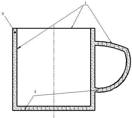
[0016] Such as figure 2 As shown, the water cup SLA product is made of transparent material, the wall thickness of the model is 5mm, and the boundary (1) (shell) is set to be 0.5mm thick, so the thickness of the photosensitive resin (2) in the middle solid area is 5-0.5*2=4mm. Considering that the bottom of the water cup model and the boundary (1) of the handle are suspended in the air, additional support (3) structures are added for them in the boundary (1).

[0017] Boundary (1) and support inside the boundary (3) are stacked layer by layer according to the conventional SLA process. At the same time, during the layer-by-layer stacking of the boundary, the photosensitive resin (3) molding raw material remains within the boundary (1), naturally forming the filling of the internal solid area.

[0018] After the conventional SLA molding is completed, the pho...


PUM


Abstract

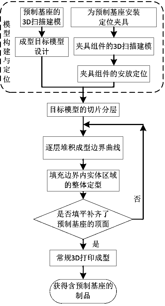
The invention discloses a 3D printing technology for shaping delayed treatment for materials in a filling area. The 3D printing technology constructs a 3D entity by stacking. The 3D printing technology is characterized in that shaping of raw materials are carried out according to boundaries and internal filling correspondingly; and when stacking target models layer by layer, only the raw materialsof the boundaries and necessary supporting structures of the boundaries are shaped, and an internal filling part remains the states of the raw materials and is not shaped, when the boundaries of thetarget models are completely constructed, the raw materials of the filling part remaining in the boundaries are integrally shaped. The molding technology enables batch molding and curing of a part ofmaterials that do not affect molding flexibility and molding accuracy, the 3D printing molding time can be shortened and the material machining efficiency is further improved.

Description

technical field [0001] The invention relates to the field of material forming and processing, especially a 3D printing forming method. Background technique [0002] Stereo Lithography Apparatus (SLA) is an earlier commercial application of 3D printing. SLA uses a specific laser to irradiate light-cured liquid materials to make the surface solidify sequentially from point to line and from line to surface to complete the processing of one layer of the forming target model, and then the lifting table supporting the molded part moves in the vertical direction for one layer thickness. distance, and then form the next layer of the target model, so that the layers are stacked to form the final product. [0003] The Selective Laser Sintering (SLS) process uses powdered materials to form shapes. In this manufacturing method, the material powder is spread on the upper surface of the formed part of the target model and flattened, and the laser beam selectively sinters the material po...

Claims


Application Information

Patent Timeline
IPC IPC(8): B29C64/118B29C64/20B29C64/268B29C64/295B29C64/30B29C64/386B33Y10/00B33Y30/00B33Y50/00
CPCB29C64/118B29C64/20B29C64/268B29C64/295B29C64/30B29C64/386B33Y10/00B33Y30/00B33Y50/00
Inventor 黄宇刚
Owner 黄宇刚
Learn More