
Direct-driving motor with single-bearing structure

A direct-drive motor and single-bearing technology, applied in the direction of electrical components, electromechanical devices, electric components, etc., can solve the problems of fixed shaft position, difficult coordination, and inability to adjust, so as to reduce materials, shorten assembly process, and increase installation matching sexual effect

Pending Publication Date: 2019-04-12
NINGBO PHASE MOTION CONTROL
View PDF11 Cites 0 Cited by
  • Summary
  • Abstract
  • Description
  • Claims
  • Application Information

AI Technical Summary

Problems solved by technology

[0002] Usually the motor adopts a double bearing structure, that is, both the front flange and the rear flange of the motor are connected with the outer ring of the bearing, and the two ends of the rotating shaft of the rotor assembly are respectively connected with the inner ring of the bearing on the front flange and with the inner ring of the bearing on the rear flange. ring connection, so that the position of the rotating shaft is fixed and cannot be adjusted. When the rotating shaft of the motor is assembled and docked with the supporting motor, it cannot be used in an environment where there is a large deviation in the assembly and docking position, and the cooperation is difficult.

Method used


Image

  • Direct-driving motor with single-bearing structure

Examples


Embodiment Construction

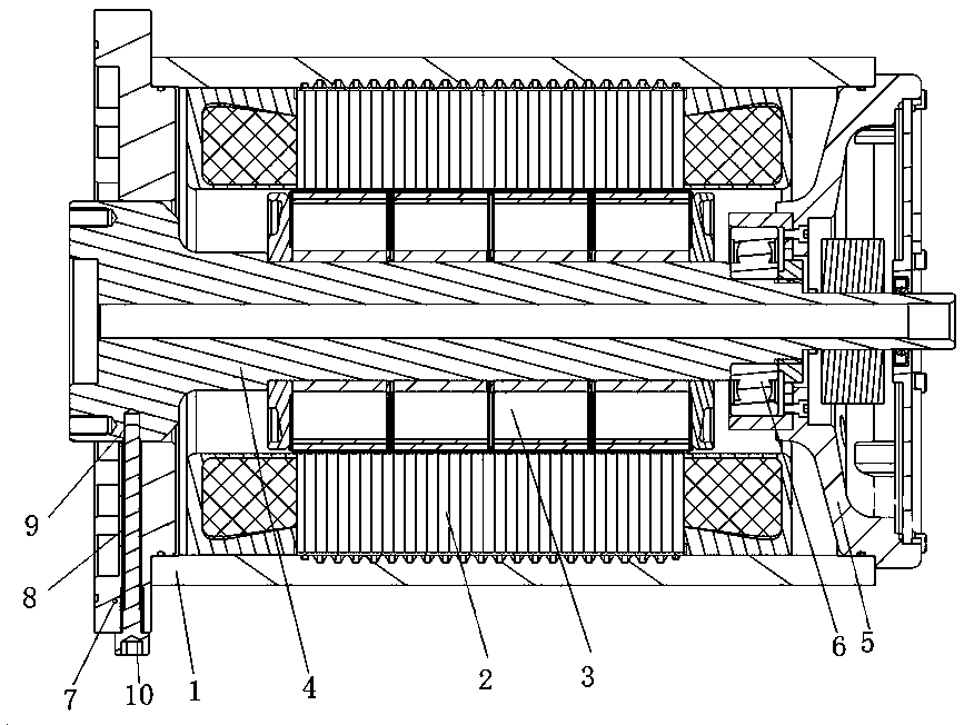
[0016] The following is based on figure 1 The specific embodiment of the present invention is further described:

[0017] see figure 1 , a direct drive motor with a single bearing structure, including a motor housing 1, a stator assembly 2, a rotor assembly 3, a front flange 7 and a rear flange 5, and the inner side of the motor housing 1 is connected with a stator assembly 2 A rotor assembly 3 is arranged inside the stator assembly 2, a front flange 7 is connected to one end of the motor housing 1, and a rear flange 5 is connected to the other end of the motor housing 1, and the rear flange The middle part of 5 is provided with a rear through hole and one side of the rear through hole is provided with a bearing chamber, the rotating shaft 4 in the rotor assembly 3 is sleeved and connected with the inner ring of the bearing 6, and one end of the rotating shaft 4 is connected from the rear The rear through hole of the flange 5 protrudes and the bearing 6 on the rotating shaft...


PUM


Abstract

The invention discloses a direct-driving motor with a single-bearing structure. The direct-driving motor comprises a motor shell, a stator component, a rotor component, a front flange and a back flange, wherein one end of the motor shell is connected with the front flange; the other end is connected with the back flange; a middle part of the back flange is provided with a back through hole; one side of the back through hole is provided with a bearing room; a rotary shaft in the rotor component is connected with a bearing inner ring; one end of the rotary shaft extends from the back through hole of the back flange, and a bearing outer ring of the rotary shaft is connected with the bearing room; the middle part of the front flange is provided with a front through hole; the other end of the rotary shaft extends from the front through hole of the front flange; the front flange is provided with a first through screw hole extending along a radial direction; the rotary shaft is provided witha second screw hole; and the first screw hole in the front flange and the second screw hole in the rotary shaft are fixedly connected with each other through a screw. Through adoption of the direct-driving motor, the position of the rotary shaft can be adjusted through the activity of a single bearing; the mounting matching degree with a matched client is improved; and the matching degree is low.The direct-driving motor can be applied to an environment in which a large deviation exists in the butt-joint position.

Description

technical field [0001] The invention relates to the technical field of motors, in particular to a direct drive motor with a single bearing structure. Background technique [0002] Usually the motor adopts a double bearing structure, that is, both the front flange and the rear flange of the motor are connected with the outer ring of the bearing, and the two ends of the rotating shaft of the rotor assembly are respectively connected with the inner ring of the bearing on the front flange and with the inner ring of the bearing on the rear flange. The ring is connected, so that the position of the rotating shaft is fixed and cannot be adjusted. When the rotating shaft of the motor is assembled and docked with the supporting motor, it cannot be used in an environment where there is a large deviation in the assembly and docking position, and the cooperation is difficult. Contents of the invention [0003] The technical problem to be solved by the present invention is to provide a...

Claims


Application Information

Patent Timeline
Patent Type & Authority Applications(China)
IPC IPC(8): H02K5/16
CPCH02K5/163
Inventor 庄超吴行超庄昊辉仇一鸣史佳楠
Owner NINGBO PHASE MOTION CONTROL
Learn More