High-precision position-adjustable code spraying device

A high-precision, coding technology, used in printing devices, printing, typewriters, etc., can solve problems such as affecting the coding effect and different coding positions.

Inactive Publication Date: 2019-04-16
NANJING WASIN FUJIKURA OPTICAL COMM LTD
View PDF18 Cites 4 Cited by
  • Summary
  • Abstract
  • Description
  • Claims
  • Application Information

AI Technical Summary

Problems solved by technology

In the existing coding process, the optical fiber cable is generally sent to the nozzle for coding through the transmission device. Because the shape of each fiber optic cable is different, the actual coding position of the nozzle is different, which affects the coding effect.

Method used


Image

  • High-precision position-adjustable code spraying device
  • High-precision position-adjustable code spraying device
  • High-precision position-adjustable code spraying device

Examples


Embodiment

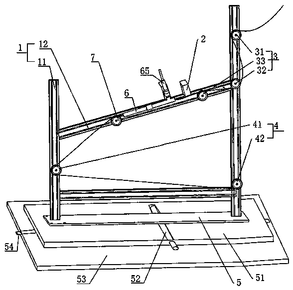
[0036] A high-precision position-adjustable inkjet device, such as figure 1 , including a support frame 1, an inkjet printer head 2 set on the support frame 1, a first transmission wheel set 3 arranged on the support frame 1 and transmitting the optical fiber to the bottom of the inkjet printer head 2, and the inkjet printer can be FT300 model, at this time, fix the nozzle 2 of the inkjet printer on the support frame 1; 2 is fixed on the connecting rod 12, and the support frame 1 is provided with a second transmission wheel set 4 that transmits the optical fiber transmitted from the bottom of the inkjet printer nozzle 2 to the winding roller.

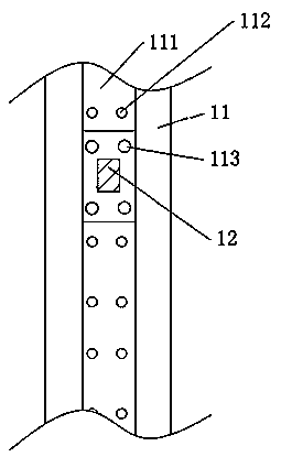
[0037] Such as figure 1 , the first transmission wheel set 3 includes the first transmission wheel 31 and the second transmission wheel 32 arranged on the pole 11 and the third transmission wheel 33 arranged on the connecting rod 12, the third transmission wheel 33 is arranged near the inkjet The position of the nozzle 2 of the inkjet...


PUM


Abstract

The invention discloses a high-precision position-adjustable code spraying device, solves the problem of capability of adjusting the position of a nozzle to meet different optical fiber code sprayingdemands, and relates to the field of code spraying for optical fibers, cables or linear products. The device comprises a support frame, a code spraying machine nozzle arranged on the support frame, and a first conveying wheel set arranged on the support frame and used for conveying optical fibers under the code spraying machine nozzle; the support frame is provided with a second conveying wheel set for conveying the optical fibers, conveyed out from the lower side of the code spraying machine nozzle, to a winding roller; a movable plate is connected under the support frame; a base plate is arranged under the movable plate; and the base plate is provided with a driving piece for shifting the movable plate in the length direction of the base plate.

Description

technical field [0001] The invention relates to the field of coding of optical fiber and cable or linear products, more specifically, it relates to a high-precision position-adjustable coding device. Background technique [0002] In the processing of optical fiber and cable products, it is often necessary to complete the coding process of printing the production date, batch number and other information on the tube body. In the existing coding process, the optical fiber cable is generally sent to the nozzle for coding through the transmission device. Because the shape of each fiber optic cable is different, the actual coding position of the nozzle is different, which affects the coding effect. Contents of the invention [0003] The object of the present invention is to provide a high-precision position-adjustable coding device, which has the advantage that the position of the nozzle can be adjusted to meet different optical fiber coding requirements. [0004] The above-men...

Claims


Application Information

Patent Timeline
Patent Type & Authority Applications(China)
IPC IPC(8): B41J3/407B41J29/00
CPCB41J3/407B41J29/00
Inventor 王振云
Owner NANJING WASIN FUJIKURA OPTICAL COMM LTD
Why Eureka
Try Eureka