
Medical medicine packaging bottle code spraying equipment

A technology for packaging bottles and medical use, which is applied in the field of coding equipment for medical pharmaceutical packaging bottles, and can solve problems such as incorrect position of coding, movement of pharmaceutical packaging bottles, and movement of medicine bottles

Pending Publication Date: 2021-07-06
高嘉浓
View PDF7 Cites 0 Cited by
  • Summary
  • Abstract
  • Description
  • Claims
  • Application Information

AI Technical Summary

Problems solved by technology

[0003] Patent application: CN201822005606.0, with a publication date of 20181130, which discloses a medical drug packaging bottle coding equipment, including a support seat, a conveying mechanism, a column, a coding machine, a support plate, a bearing, a driven tooth, and an ink outlet When parts such as the ink delivery tube and the coding gun are in use, the motor rotates to drive the transmission gear to rotate synchronously. At this moment, the driven rotation of the meshing connection drives the screw rod to rotate step by step. The board and the coding gun move up and down, so as to realize the adjustment of the gap distance between the bottle and the upper end of the conveying mechanism, which is convenient for the precise coding operation of the packaging bottles of different sizes, saves time and effort, and improves the quality of the coding. It is conducive to promotion and popularization. However, when using this equipment, due to the large range of spraying in the process of painting, it is easy to move the medicine bottle being sprayed, and it is easy to make the position of the spraying wrong.
[0004] To sum up, when people spray codes on pharmaceutical packaging bottles, due to the large range of spraying codes, it is easy to move the pharmaceutical packaging bottles being sprayed. , so that it will not walk around the medical drug packaging bottle inkjet equipment

Method used


Image

  • Medical medicine packaging bottle code spraying equipment
  • Medical medicine packaging bottle code spraying equipment
  • Medical medicine packaging bottle code spraying equipment

Examples


Embodiment 1

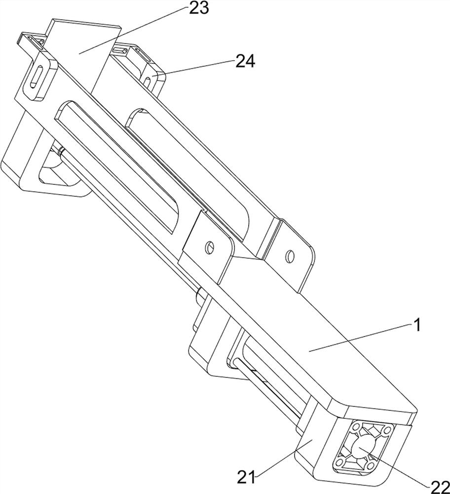
[0062] A coding equipment for medical packaging bottles, such as figure 1 As shown, it includes a bottom plate 1, a pushing mechanism 2, a feeding mechanism 3 and a coding mechanism 4. A bottom plate 1 is placed on the ground, and a pushing mechanism 2 is arranged between the upper and lower sides of the bottom plate 1. Between the pushing mechanism 2 and the bottom plate 1 A blanking mechanism 3 is provided, and a coding mechanism 4 is provided on the rear side of the bottom plate 1 .

[0063]When people need to spray codes on pharmaceutical packaging bottles, people place the packaging bottles that need to be sprayed in the unloading mechanism 3, and then people manually rotate the unloading mechanism 3 to unload the pharmaceutical packaging bottles in the unloading mechanism 3 to the bottom plate 1, people open the pushing mechanism 2, so that the pushing mechanism 2 pushes the medicine packaging bottle on the bottom plate 1, when the medicine packaging bottle is pushed to ...

Embodiment 2

[0065] On the basis of Example 1, such as figure 2 As shown, the pushing mechanism 2 includes a fixed frame 21, a cylinder 22, a pusher plate 23 and a top plate 24, and the bottom of the bottom plate 1 is evenly provided with a fixed frame 21, and the number of the fixed frames 21 is three, and the two fixed frames 21 on the right side Cylinder 22 is installed between, and the telescoping link of cylinder 22 is connected with pusher plate 23, and pusher plate 23 cooperates with base plate 1, and both sides before and after pusher plate 23 are all provided with top plate 24, and top plate 24 cooperates with base plate 1.

[0066] When the medicine packaging bottle is unloaded on the bottom plate 1 by the unloading mechanism 3, people open the cylinder 22, so that the telescopic rod of the cylinder 22 drives the pusher plate 23 to move to the right, and then drives the top plate 24 to move to the right, so that the top plate 24 slides on the bottom plate 1, thereby driving the ...

Embodiment 3

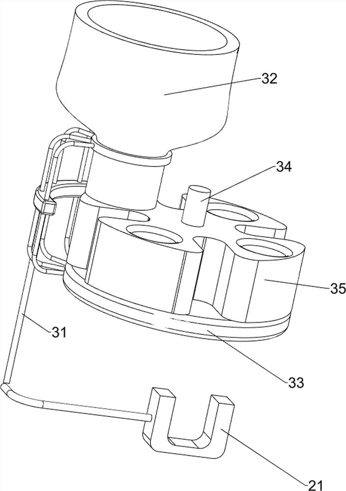
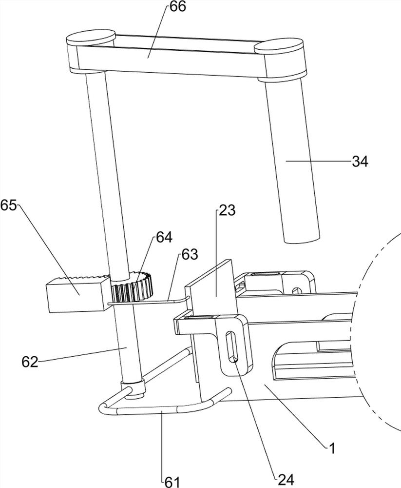
[0068] On the basis of Example 2, such as figure 1 , image 3 , Figure 4 , Figure 5 , Figure 6 and Figure 7 As shown, the blanking mechanism 3 includes a first mounting frame 31, a blanking bucket 32, a load-bearing plate 33, a first rotating shaft 34 and a perforated turntable 35, and the front portion of the fixed frame 21 on the left side is provided with a first mounting frame 31, The first mounting frame 31 is equipped with a lower material bucket 32, the rear side of the first mounting frame 31 is provided with a load bearing plate 33, the middle part of the load bearing plate 33 is rotatably provided with a first rotating shaft 34, and the load bearing plate 33 is rotatably provided with a perforated turntable 35 , the perforated turntable 35 is connected to the first rotating shaft 34 .

[0069] When people need to spray code on pharmaceutical packaging bottles, people place a plurality of pharmaceutical packaging bottles that need to be sprayed in the materia...


PUM


Abstract

The invention relates to packaging bottle code spraying equipment, in particular to medical medicine packaging bottle code spraying equipment. According to the medical medicine packaging bottle code spraying equipment, medicine packaging bottles which are subjected to code spraying can be clamped, so that the medicine packaging bottles cannot move freely. The medical medicine packaging bottle code spraying equipment comprises a bottom plate, a pushing mechanism, a discharging mechanism and a code spraying mechanism; the bottom plate is placed on the ground, and the pushing mechanism is arranged between the upper side and the lower side of the bottom plate; the discharging mechanism is arranged between the pushing mechanism and the bottom plate; the code spraying mechanism is arranged on the lateral portion of the bottom plate. According to the medical medicine packaging bottle code spraying device, the pushing mechanism and the discharging mechanism are matched with the code spraying mechanism, so that a material pushing plate pushes the medicine packaging bottles discharged by a rotating disc with holes, and a code spraying assembly sprays codes on the medicine packaging bottles, so that manpower consumed by people for spraying the codes on the medicine packaging bottles is less, and the effect that people can conveniently spray the codes on the medicine packaging bottles is achieved.

Description

technical field [0001] The invention relates to a coding equipment for packaging bottles, in particular to a coding equipment for packaging bottles of medical medicines. Background technique [0002] At present, in the production of medical drugs, it is necessary to put the drugs into the drug packaging bottles. Since many drug packaging bottles on the market are generally similar, it is necessary for people to spray codes on the surface of the required drug packaging bottles to facilitate people's identification. Most of the codes are easily scratched off, and there are few devices that can spray codes on medicine bottles. [0003] Patent application: CN201822005606.0, the publication date is 20181130, which discloses a medical drug packaging bottle coding equipment, including a support seat, a conveying mechanism, a column, a coding machine, a support plate, a bearing, a driven tooth, and an ink outlet When parts such as the ink delivery tube and the coding gun are in use...

Claims


Application Information

Patent Timeline
IPC IPC(8): B65B61/26B65B65/00B65B35/26
CPCB65B61/26B65B35/26B65B65/00
Inventor 高嘉浓
Owner 高嘉浓
Learn More