
A coding device for a flexible printed circuit board

A flexible printing and circuit board technology, applied in the directions of printed circuits, printed circuit manufacturing, printing devices, etc., can solve the problems of inconvenient circuit board-guided protective processing, inconvenient circuit board transmission and collection, and inconvenient replacement of limit devices, etc. The effect of facilitating coding and transportation, reducing labor costs and reducing labor input

Active Publication Date: 2022-03-08
益阳维胜科技有限公司
View PDF17 Cites 0 Cited by
  • Summary
  • Abstract
  • Description
  • Claims
  • Application Information

AI Technical Summary

Problems solved by technology

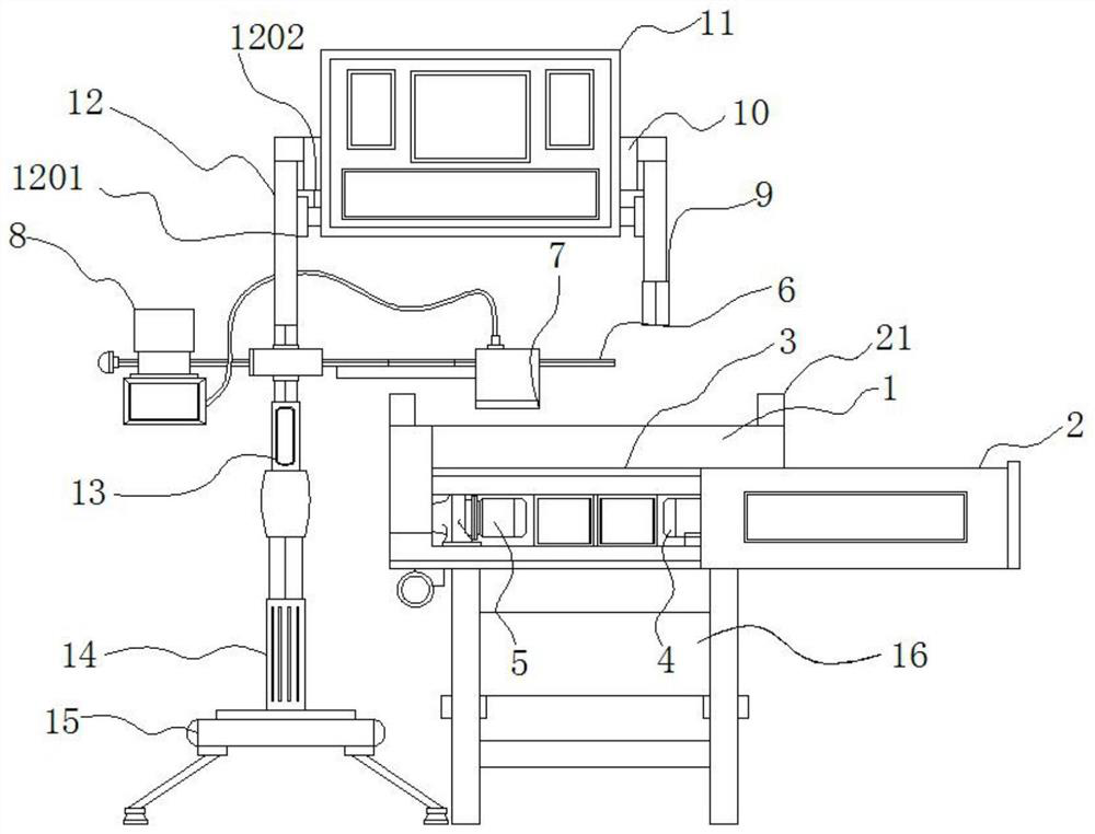
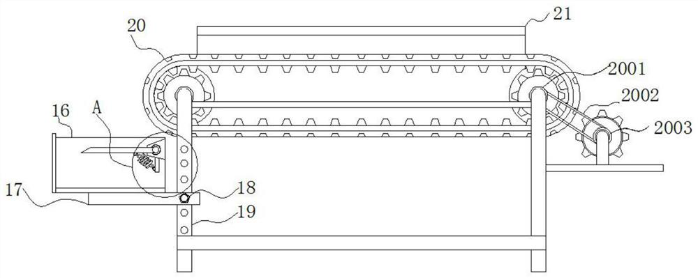
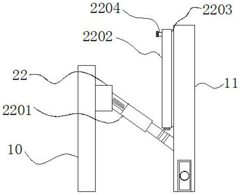
[0004] The object of the present invention is to provide a coding device for flexible printed circuit boards, so as to solve the problem that it is inconvenient for users to limit the printed circuit boards that need to be coded during the use of the coding device proposed in the above-mentioned background technology, and It is inconvenient to replace the limit device according to the size of the circuit board, which brings inconvenience to the use of the user, and it is inconvenient for the user to transfer and collect the circuit board after the coding is completed during use. Able to carry out guided protective treatment on dropped circuit boards, which is prone to frictional damage due to gravity falling

Method used


Image

  • A coding device for a flexible printed circuit board
  • A coding device for a flexible printed circuit board
  • A coding device for a flexible printed circuit board

Examples


Embodiment Construction

[0026] The following will clearly and completely describe the technical solutions in the embodiments of the present invention with reference to the accompanying drawings in the embodiments of the present invention. Obviously, the described embodiments are only some of the embodiments of the present invention, not all of them. Based on the embodiments of the present invention, all other embodiments obtained by persons of ordinary skill in the art without making creative efforts belong to the protection scope of the present invention.

[0027] In the description of the present invention, unless otherwise stated, the meaning of "plurality" is two or more; the terms "upper", "lower", "left", "right", "inner", "outer" , "front end", "rear end", "head", "tail", etc. indicate the orientation or positional relationship based on the orientation or positional relationship shown in the drawings, and are only for the convenience of describing the present invention and simplifying the descr...


PUM


Abstract

The invention discloses a coding device for a flexible printed circuit board, which relates to the technical field of coding machines, and includes a working platform and a base. Both ends of the working platform are provided with protective side plates. The front end is equipped with a second motor, and one end inside the second motor is provided with a transmission device. In the present invention, through the setting of the guide device, the limit fixing block, the limit sleeve groove, the rotating shaft, the hanging ring, the fixing spring and the connection riser, when the printed circuit board falls from the surface of the conveying device, the limit can be used. The interaction between the fixed block, the limit sleeve groove and the rotating shaft adjusts the angle of the guide device, and when the printed circuit board is dropped, the force exerted on the guide device will exert a certain force on the fixed spring stretched at the bottom, thereby printing The circuit board can use the function of the guiding device to perform force unloading treatment and then fall to the inside of the storage frame, effectively reducing the damage to the printed circuit board due to gravity during transportation.

Description

technical field [0001] The invention relates to the field of coding technology, in particular to a coding device for a flexible printed circuit board. Background technique [0002] Printed circuit boards, also known as printed circuit boards, are providers of electrical connections for electronic components. Its development has a history of more than 100 years; its design is mainly layout design; the main advantage of using circuit boards is that it greatly reduces wiring and assembly errors, and improves automation and production labor rates. Printed circuit boards, also known as printed circuit boards and printed circuit boards, need to be coded and marked during the processing of printed circuit boards to provide convenience for subsequent use. [0003] The coding device on the market is inconvenient for the user to limit the printed circuit board that needs to be coded during use, and it is inconvenient to replace the limiting device according to the size of the circuit...

Claims


Application Information

Patent Timeline
Patent Type & Authority Patents(China)
IPC IPC(8): B41J3/407B41J29/00H05K3/00B65G47/34
CPCB41J3/407B41J29/00H05K3/00B65G47/34
Inventor 彭韧张国兴唐川
Owner 益阳维胜科技有限公司
Learn More