
Elevator suspension sheave device and method for mounting suspension sheave device

A technology of hanging wheels and elevators, applied in the directions of transportation, packaging, elevators, etc., can solve the problem of beams not being arranged in parallel, and achieve the effect of changing the installation angle

Active Publication Date: 2019-04-16
MITSUBISHI ELECTRIC CORP
View PDF6 Cites 0 Cited by
  • Summary
  • Abstract
  • Description
  • Claims
  • Application Information

AI Technical Summary

Problems solved by technology

However, in such an elevator apparatus, when making the front end of the beam protrude from the car, due to the gap between the car and the hoistway, the guide rails installed in the hoistway, etc., the

Method used


Image

  • Elevator suspension sheave device and method for mounting suspension sheave device
  • Elevator suspension sheave device and method for mounting suspension sheave device
  • Elevator suspension sheave device and method for mounting suspension sheave device

Examples


Embodiment approach 1

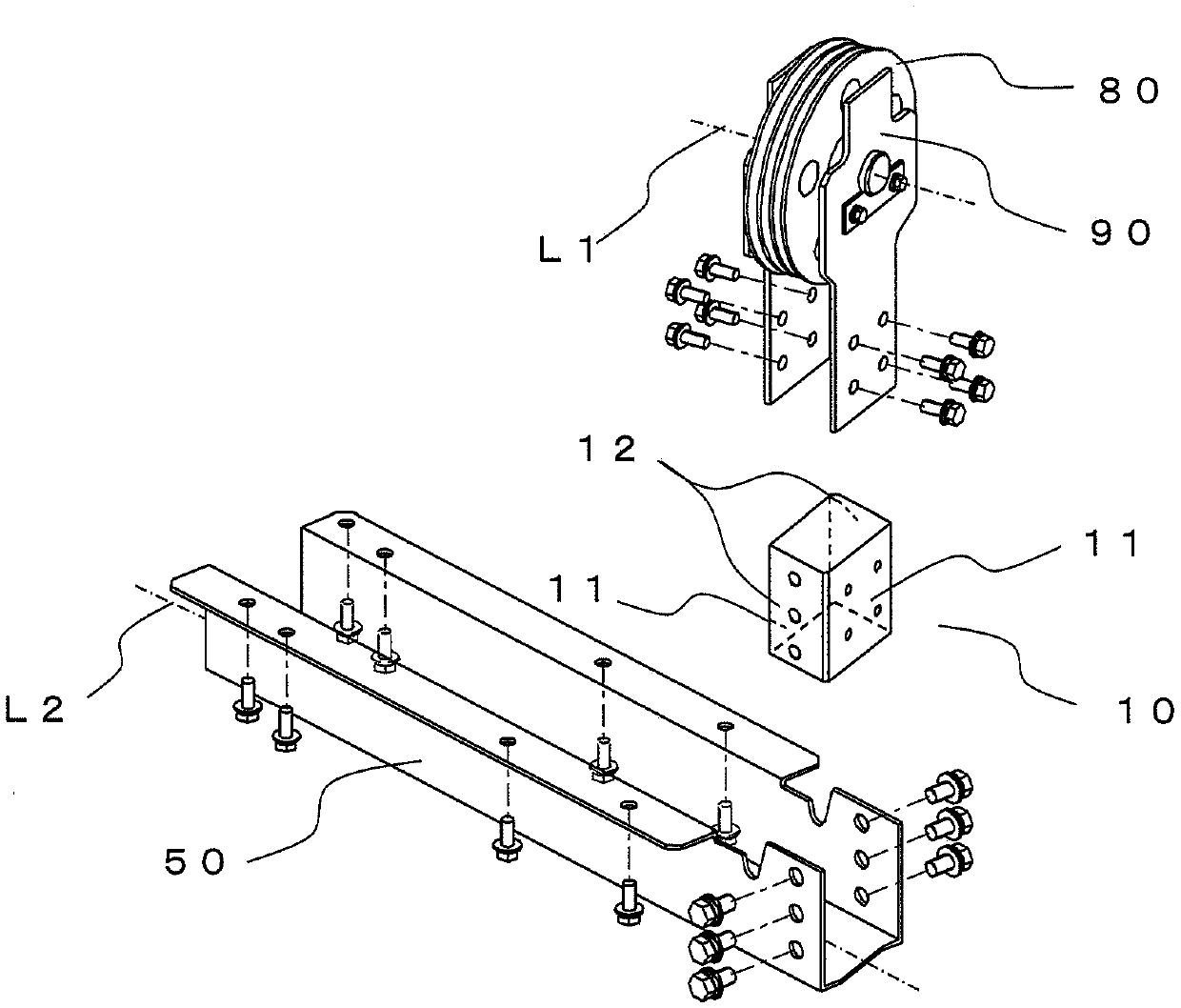
[0024] figure 1 It is a configuration diagram showing the suspension wheel device in Embodiment 1 of the present invention. Such as figure 1 As shown, the suspension wheel device has a support plate 90 for supporting the suspension wheel 80 , a beam 50 , and a connection body 10 for connecting the support plate 90 and the beam 50 . The support plate 90 is constituted by a pair of plate-shaped members, and supports the suspension pulley 80 so that the suspension pulley 80 is sandwiched by the pair of plate-shaped members from the direction of the rotation axis L1 of the suspension pulley 80 . Four through-holes for fastening the support plate 90 to the coupling body 10 are respectively provided at the ends of a pair of plate-shaped members constituting the support plate 90 .

[0025] The connecting body 10 is constituted by a hexahedron, the cross-section in the horizontal direction parallel to the top surface forms a parallelogram, and the adjacent side surfaces form a non-p...


PUM


Abstract

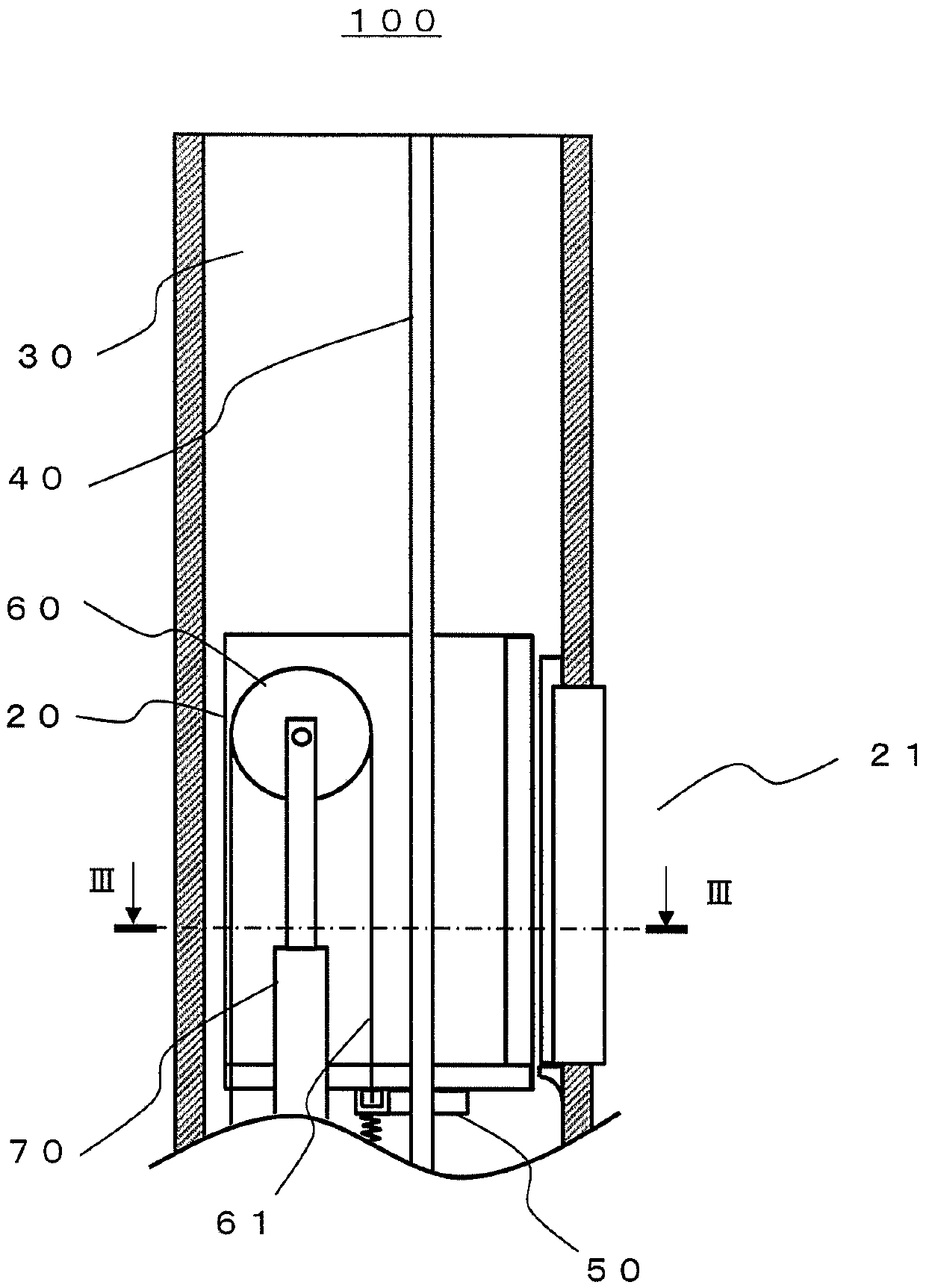
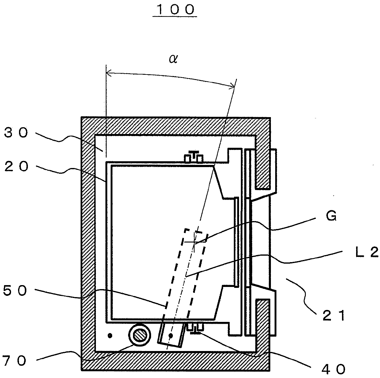
A suspension sheave device, having: a suspension sheave (80) around which a rope is wound to raise and lower a cage (20); support plates (90) for supporting the rotation shaft (L1) of the suspension sheave (80); a suspension sheave beam (50) mounted on the cage (20); and a linking body (10), formed as a polyhedron, for linking the support plates (90) and the suspension sheave beam (50). The linking body (10) has support plate mounting surfaces (11) on which the support plates (90) are mounted, and beam mounting surfaces (12) mounted on the suspension sheave beam (50). When the support plates (90) are mounted on the support plate mounting surfaces (11) of the linking body (10) fixed to the suspension sheave beam (50) via the beam mounting surfaces (12), the rotation shaft (L1) of the suspension sheave (80) is positioned at a predefined angle, in the horizontal plane, relative to the longitudinal direction (L2) of the suspension sheave (50).

Description

technical field [0001] The present invention relates to a hanging sheave installation device and a hanging sheave installation method. When upgrading an elevator, etc., the beams of the existing elevator device are used or replaced to install the hanging sheaves. Background technique [0002] Conventionally, there is an elevator apparatus having a structure in which a beam is attached to the upper or lower portion of the car so that its longitudinal direction is parallel to the back or side of the car, and the ends of the ropes are fixed to the beam. In addition, in the structure where the beam is attached to the lower part of the car, there is a structure in which the tip of the beam protrudes from the lower part of the car toward the wall of the hoistway, and the end of the rope is fixed to the tip of the protruding beam. However, in such an elevator apparatus, when making the front end of the beam protrude from the car, due to the gap between the car and the hoistway, the...

Claims


Application Information

Patent Timeline
IPC IPC(8): B66B7/06
CPCB66B7/06
Inventor 加藤岳广高桥良直本村晃一森仓大树
Owner MITSUBISHI ELECTRIC CORP
Learn More