Thin steel plate bending device

A technology of bending device and thin steel plate, applied in the field of bending device, can solve problems such as low work efficiency, and achieve the effect of high work efficiency and improvement of work efficiency

Active Publication Date: 2019-04-19
广西盛隆钢铁材料研究院有限公司
View PDF7 Cites 17 Cited by
  • Summary
  • Abstract
  • Description
  • Claims
  • Application Information

AI Technical Summary

Problems solved by technology

[0003] In order to overcome the shortcoming that only a small amount of thin steel plates can be bent due to limited human strength, the work efficiency is low, and only one side of the thin steel plates can be bent at a time. Therefore, the technical problem of the present invention is: to provide a A steel plate bender that can bend a large number of thin steel plates instead of humans, has high work efficiency, and can bend both sides of the thin steel plate at the same time

Method used


Image

  • Thin steel plate bending device
  • Thin steel plate bending device
  • Thin steel plate bending device

Examples


Embodiment 1

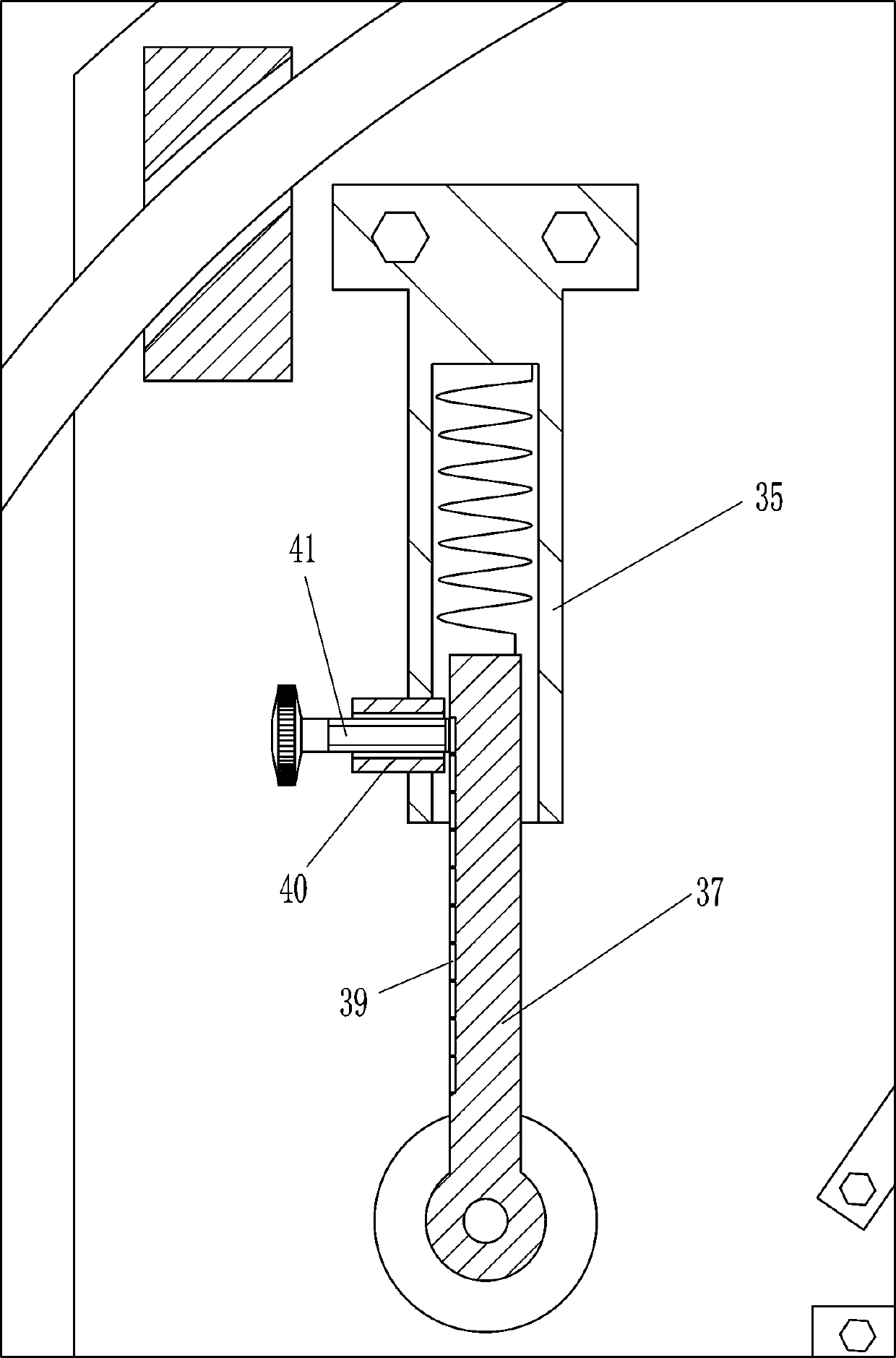
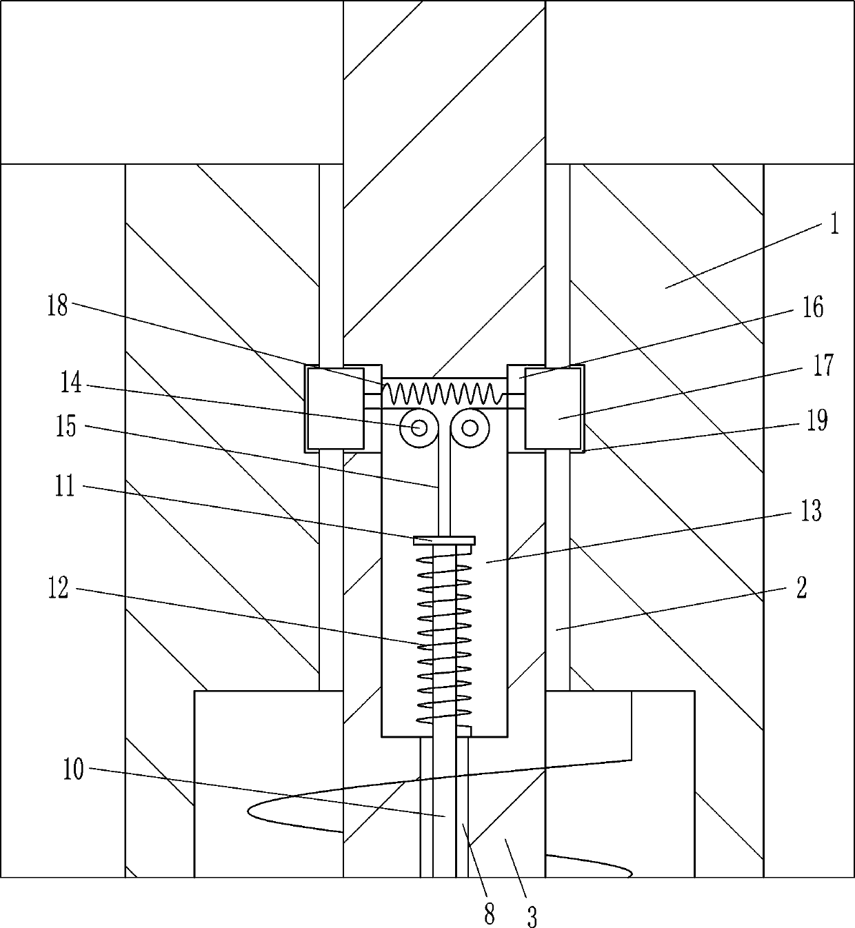
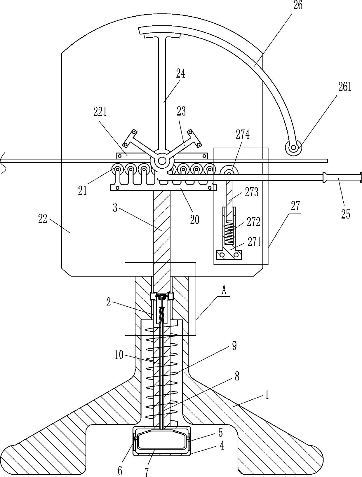
[0019] A sheet metal bender, such as Figure 1-2 As shown, it includes a first support 1, a guide rod 3, a hollow frame 4, a slide rail 5, a slider 6, a pedal 7, a first spring 9, a first slide bar 10, a baffle plate 11, a second spring 12, Orientation wheel 14, stay cord 15, slide block 17, third spring 18, support plate 20, first roller 21, fixed plate 22, limit plate 221, second support 23, swing lever 24, handle 25, arc Shape bar 26, second roller 261 and telescopic device 27, have guide hole 2 in the middle of the first support 1, slide type is provided with guide rod 3 in the guide hole 2, guide rod 3 bottom is provided with hollow frame 4, guide rod 3 Connect with the hollow frame 4 by welding, the first spring 9 is connected between the top of the hollow frame 4 and the inner top of the first support 1, the left and right walls of the hollow frame 4 are provided with slide rails 5, the left and right sides Slide rails 5 are provided with sliding blocks 6, and pedals 7...

Embodiment 2

[0021] A sheet metal bender, such as Figure 1-2As shown, it includes a first support 1, a guide rod 3, a hollow frame 4, a slide rail 5, a slider 6, a pedal 7, a first spring 9, a first slide bar 10, a baffle plate 11, a second spring 12, Orientation wheel 14, stay cord 15, slide block 17, third spring 18, support plate 20, first roller 21, fixed plate 22, limit plate 221, second support 23, swing lever 24, handle 25, arc Shape bar 26, second roller 261 and telescopic device 27, have guide hole 2 in the middle of the first support 1, slide type is provided with guide rod 3 in guide hole 2, guide rod 3 bottom is provided with hollow frame 4, hollow frame 4 The first spring 9 is connected between the top and the inner top of the first bearing 1, and the left and right walls in the hollow frame 4 are provided with slide rails 5, and the slide rails 5 on the left and right sides are all slidably provided with slide blocks 6, and the left and right A pedal 7 is connected between ...

Embodiment 3

[0024] A sheet metal bender, such as Figure 1-3 As shown, it includes a first support 1, a guide rod 3, a hollow frame 4, a slide rail 5, a slider 6, a pedal 7, a first spring 9, a first slide bar 10, a baffle plate 11, a second spring 12, Orientation wheel 14, stay cord 15, slide block 17, third spring 18, support plate 20, first roller 21, fixed plate 22, limit plate 221, second support 23, swing lever 24, handle 25, arc Shape bar 26, second roller 261 and telescopic device 27, have guide hole 2 in the middle of the first support 1, slide type is provided with guide rod 3 in guide hole 2, guide rod 3 bottom is provided with hollow frame 4, hollow frame 4 The first spring 9 is connected between the top and the inner top of the first bearing 1, and the left and right walls in the hollow frame 4 are provided with slide rails 5, and the slide rails 5 on the left and right sides are all slidably provided with slide blocks 6, and the left and right A pedal 7 is connected between...


PUM


Abstract

The invention relates to a bending device, in particular to a thin steel plate bending device. According to the technical aim, the thin steel plate bending device can replace a person to bend a largenumber of thin steel plates, the work efficiency is high, and the two sides of the thin steel plates can be simultaneously bent. According to the technical scheme, the thin steel plate bending devicecomprises a first support, a guide rod, a hollow frame, a slide rail, a slider, a pedal, a first spring, a first slide bar, a baffle, a second spring, a directional wheel, a drawstring and the like; and a guide hole is formed in the middle of the first support, the guide rod is arranged in the guide hole in a sliding manner, and the hollow frame is arranged at the bottom of the guide rod. Throughthe effect of a second roller, the thin steel plates can be bent, a telescopic device can limit the bending degree of the thin steel plates, influences of too large bending angles of the thin steel plates on subsequent use are avoided, the person does not need to bend the thin steel plates with the both hands, time and labor are saved, and the work efficiency is very high.

Description

technical field [0001] The invention relates to a bender, in particular to a thin steel plate bender. Background technique [0002] In building construction, it is often necessary to use a large amount of materials, and thin steel plates are one of them. However, some of the thin steel plates required for construction are bent, and the thin steel plates need to be bent before use. Usually, people use both hands Bending thin steel plates, due to limited human strength, can only bend a small amount of thin steel plates, the work efficiency is low, and only one side of the thin steel plates can be bent at a time, so multiple people are required to bend the thin steel plates at the same time Bending, and two people bend both sides of a thin steel plate at the same time, so the labor cost is high. Contents of the invention [0003] In order to overcome the shortcoming that only a small amount of thin steel plates can be bent due to limited human strength, the work efficiency i...

Claims


Application Information

Patent Timeline
Patent Type & Authority Applications(China)
IPC IPC(8): B21D5/04
CPCB21D5/04
Inventor 彭友江
Owner 广西盛隆钢铁材料研究院有限公司
Why Eureka
Try Eureka