Spatial trajectory transition method, system and robot for industrial robot
An industrial robot and trajectory technology, applied in the field of robotics, can solve the problem that the transition method cannot make a smooth transition, and achieve the effect of a smooth transition
- Summary
- Abstract
- Description
- Claims
- Application Information
AI Technical Summary
Problems solved by technology
Method used
Image
Examples
Embodiment 1
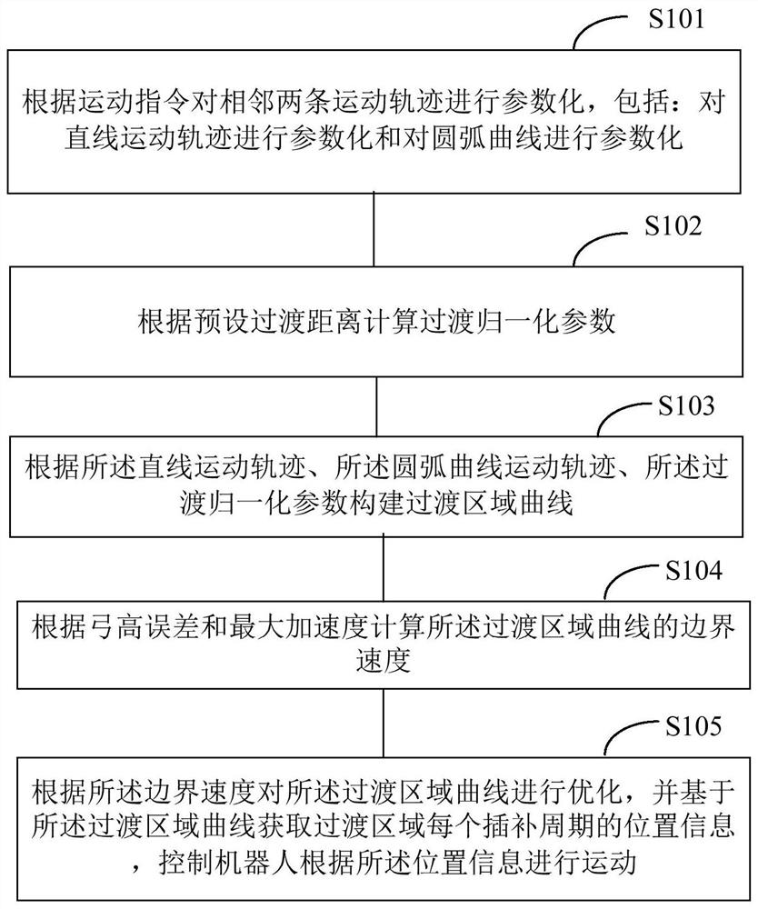
[0043] like figure 1 As shown, the present embodiment provides a space trajectory transition method for an industrial robot, which specifically includes:
[0044] Step S101: Parametrizing two adjacent motion trajectories according to the motion command, including: parametrizing the linear motion trajectory and parametrizing the arc curve.
[0045] In a specific application, by parameterizing two adjacent motion commands, that is, parameterizing the motion trajectory corresponding to the motion commands. The above-mentioned motion trajectory includes linear motion trajectory and arc motion trajectory.
[0046] In a specific application, the linear motion trajectory is parameterized, and the parameter equation is: f(s)=p start +s·(p end -p start );
[0047] Among them, s∈[0,1] is the normalization parameter, p start and p end are the start and end points of the line, respectively.
[0048] In a specific application, the arc motion track is parameterized, and the paramete...
Embodiment 2
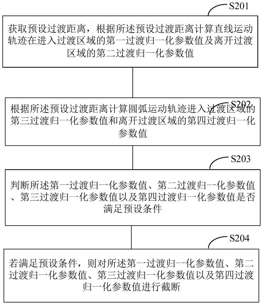
[0073] like image 3 As shown, in this embodiment, step S102 in Embodiment 1 specifically includes:
[0074] Step S201: Obtain a preset transition distance, and calculate the first transition normalization parameter value of the linear motion trajectory entering the transition region and the second transition normalization parameter value of leaving the transition region according to the preset transition distance.
[0075] In a specific application, the calculation formula for calculating the normalized parameter value of the first transition of the linear motion trajectory entering the transition area according to the preset transition distance is: Among them, d z is the preset transition distance, L 1 is the total length of the linear motion trajectory entering the transition region.
[0076] In a specific application, the calculation formula for calculating the second transition normalization parameter value of the linear motion trajectory leaving the transition area a...
Embodiment 3
[0085] like Figure 4 As shown, in this embodiment, step S104 in Embodiment 1 specifically includes:
[0086] Step S301: Acquire a bow height error, and calculate a first boundary velocity of the transition region curve according to the bow height error.
[0087] In specific applications, set and according to the bow height error δ max A first boundary velocity of the transition region curve is calculated. The calculation formula for calculating the first boundary velocity of the transition zone curve is: Among them, ρ is the maximum value of the curvature of the transition curve, T s Interpolation period for the transition curve.
[0088] Step S302: Obtain the maximum acceleration, and calculate the second boundary velocity of the transition region curve according to the maximum acceleration.
[0089] In specific applications, set and according to the maximum acceleration A max Computes the second boundary velocity of the curve in the transition region. The formula fo...
PUM
 Abstract
Description
Claims
Application Information
 - R&D
- Intellectual Property
- Life Sciences
- Materials
- Tech Scout
- Unparalleled Data Quality
- Higher Quality Content
- 60% Fewer Hallucinations
Browse by: Latest US Patents, China's latest patents, Technical Efficacy Thesaurus, Application Domain, Technology Topic, Popular Technical Reports.
© 2025 PatSnap. All rights reserved.Legal|Privacy policy|Modern Slavery Act Transparency Statement|Sitemap|About US| Contact US: help@patsnap.com


