Space trajectory transition method and system for industrial robot, and robot

An industrial robot and trajectory technology, applied in the field of robotics, can solve the problem that the transition method cannot make a smooth transition, and achieve the effect of a smooth transition

Active Publication Date: 2019-04-19
SHENZHEN YUEJIANG TECH CO LTD
View PDF4 Cites 14 Cited by
  • Summary
  • Abstract
  • Description
  • Claims
  • Application Information

AI Technical Summary

Problems solved by technology

[0005] In view of this, the embodiment of the present invention provides a space trajectory transition method, system and robot of an industrial robot to solve the problem that the current transition method of the space trajectory of an industrial robot cannot be smoothly transitioned

Method used


Image

  • Space trajectory transition method and system for industrial robot, and robot
  • Space trajectory transition method and system for industrial robot, and robot
  • Space trajectory transition method and system for industrial robot, and robot

Examples


Embodiment 1

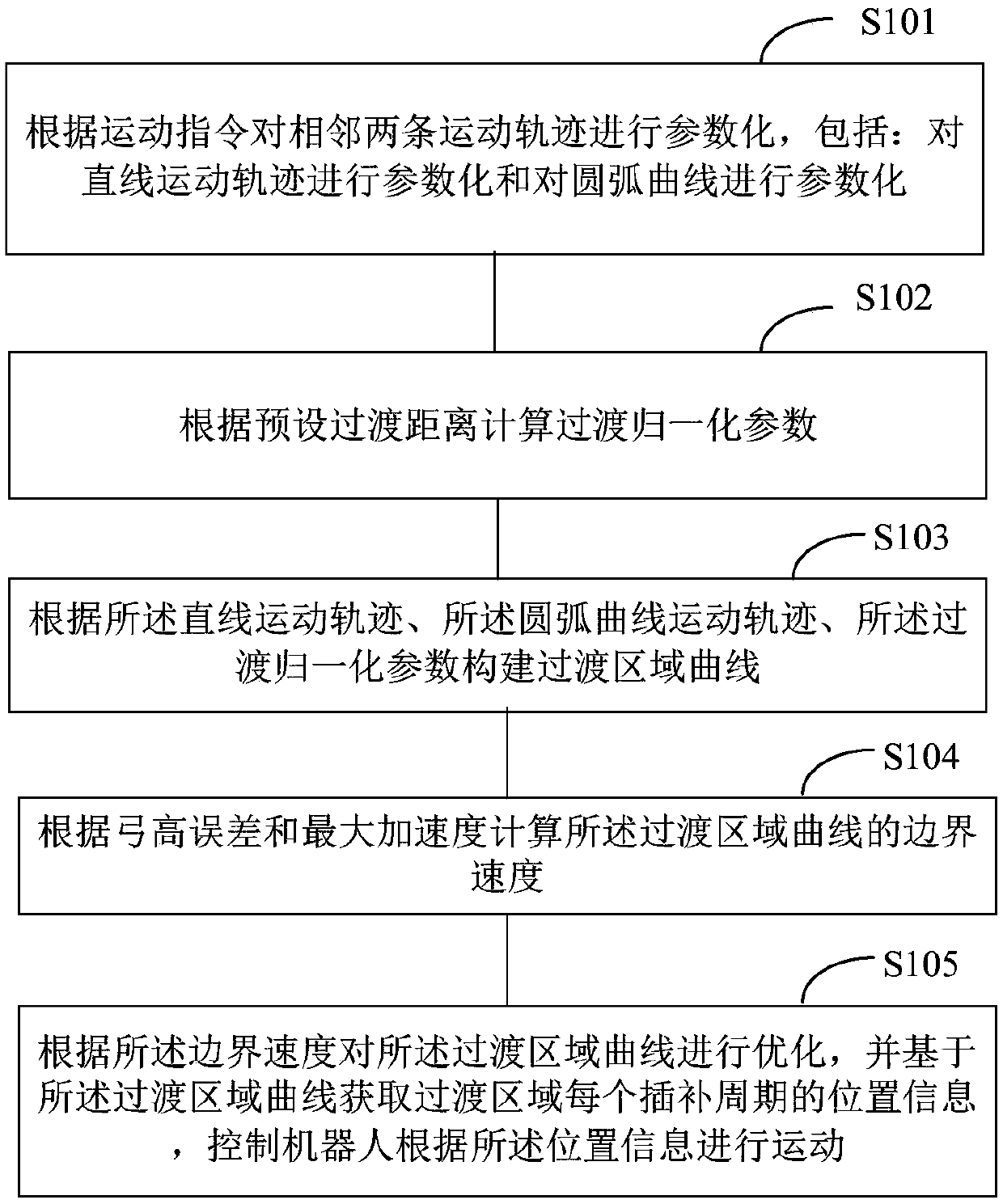
[0043] Such as figure 1 As shown, the present embodiment provides a space trajectory transition method for an industrial robot, which specifically includes:

[0044] Step S101: Parametrizing two adjacent motion trajectories according to the motion command, including: parametrizing the linear motion trajectory and parametrizing the arc curve.

[0045] In a specific application, by parameterizing two adjacent motion commands, that is, parameterizing the motion trajectory corresponding to the motion command. The above-mentioned motion trajectory includes linear motion trajectory and arc motion trajectory.

[0046] In a specific application, the linear motion trajectory is parameterized, and the parameter equation is: f(s)=p start +s·(p end -p start );

[0047] Among them, s∈[0,1] is the normalization parameter, p start and p end are the start and end points of the line, respectively.

[0048] In a specific application, the arc motion track is parameterized, and the parame...

Embodiment 2

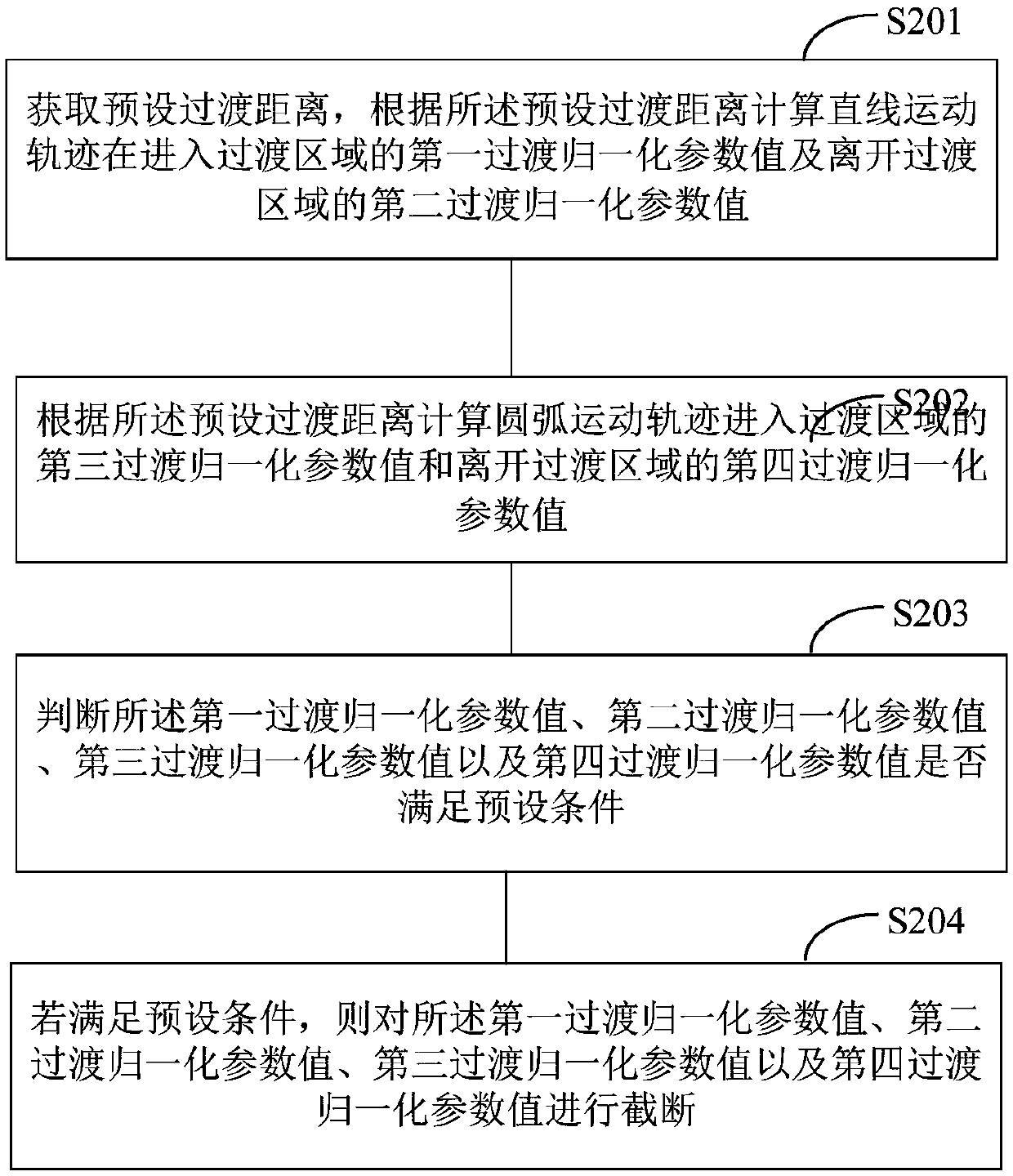
[0073] Such as image 3 As shown, in this embodiment, step S102 in Embodiment 1 specifically includes:

[0074] Step S201: Obtain a preset transition distance, and calculate the first transition normalization parameter value of the linear motion trajectory entering the transition region and the second transition normalization parameter value of leaving the transition region according to the preset transition distance.

[0075] In a specific application, the calculation formula for calculating the normalized parameter value of the first transition of the linear motion trajectory entering the transition area according to the preset transition distance is: Among them, d z is the preset transition distance, L 1 is the total length of the linear motion trajectory entering the transition region.

[0076] In a specific application, the calculation formula for calculating the second transition normalization parameter value of the linear motion trajectory leaving the transition are...

Embodiment 3

[0085] Such as Figure 4 As shown, in this embodiment, step S104 in Embodiment 1 specifically includes:

[0086] Step S301: Acquire a bow height error, and calculate a first boundary velocity of the transition region curve according to the bow height error.

[0087] In specific applications, set and according to the bow height error δ max A first boundary velocity of the transition region curve is calculated. The calculation formula for calculating the first boundary velocity of the transition zone curve is: Among them, ρ is the maximum value of the curvature of the transition curve, T s Interpolation period for the transition curve.

[0088] Step S302: Obtain the maximum acceleration, and calculate the second boundary velocity of the transition region curve according to the maximum acceleration.

[0089] In specific applications, set and according to the maximum acceleration A max Computes the second boundary velocity of the curve in the transition region. The formula...


PUM


Abstract

The invention is applicable to the technical field of robots, and provides a space trajectory transition method and system for an industrial robot and the robot. The space trajectory transition methodcomprises the following steps of: constructing a transition region curve according to a linear motion trajectory, an arc curve motion trajectory and transition normalization parameters, calculating the boundary speed of the transition region curve according to a bow height error and a maximum acceleration, and optimizing the transition region curve according to the boundary speed, obtaining position information of each interpolation period of the transition region based on the transition region curve and controlling the robot to move according to the position information. By constructing thetransition region curve and limiting the boundary speed, the transition trajectory can be kept consistent at a low speed and a high speed. Since the trajectory speed of the transition region is determined according to the bow height error and the maximum acceleration, the transition speed can be ensured to be within the allowable range, and the curvature of the transition trajectory and the original trajectory changes continuously at the junction, thus realizing smooth transition.

Description

technical field [0001] The invention belongs to the technical field of robots, and in particular relates to a space trajectory transition method, system and robot of an industrial robot. Background technique [0002] The motion of an industrial robot in its workspace is composed of various trajectories generated by multiple motion commands input by the user. The trajectories generated by each motion command (such as linear motion trajectories and circular arc motion trajectories are smooth, but there will be sudden changes at the connection of each trajectory due to speed changes, resulting in severe jitter. In order to minimize sudden changes, usually The transition is realized by constructing a transition curve, and the amount of mutation is reduced by connecting the transition track with the original track. [0003] The current method of constructing the transition curve includes: using the planning time as the transition parameter, and constructing the transition curve ...

Claims


Application Information

Patent Timeline
Patent Type & Authority Applications(China)
IPC IPC(8): B25J9/16
CPCB25J9/1664
Inventor 林炯辉朗需林刘培超曹林攀林俊凯
Owner SHENZHEN YUEJIANG TECH CO LTD
Why Eureka
Try Eureka