Boundary pile locator for land planning

A locator and boundary stake technology, which is applied in the field of boundary stake locators for land planning, can solve the problems of labor-intensive, misunderstanding and the like, and achieve the effect of reducing manpower

Active Publication Date: 2019-04-19
JIANGXI COLLEGE OF APPLIED TECH
View PDF7 Cites 5 Cited by
  • Summary
  • Abstract
  • Description
  • Claims
  • Application Information

AI Technical Summary

Problems solved by technology

[0002] In order to facilitate the installation of boundary posts, people need to locate them, mark the installation place, and then install them. At present, when installing boundary posts, people usually use hoes or shovels to locate and mark the boundary posts. However, shoveling or digging out a positioning and marking at the installation place is easy to be misunderstood, because the marks made by shovels and hoes are very common, so misunderstandings are easy to occur, and it takes a long time to mark with shovels and hoes at the same time , which requires a lot of manpower

Method used


Image

  • Boundary pile locator for land planning
  • Boundary pile locator for land planning
  • Boundary pile locator for land planning

Examples


Embodiment 1

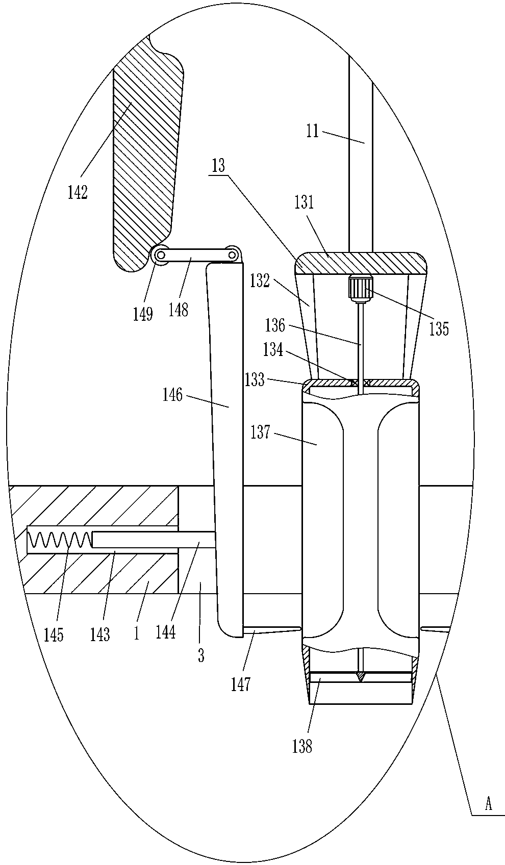
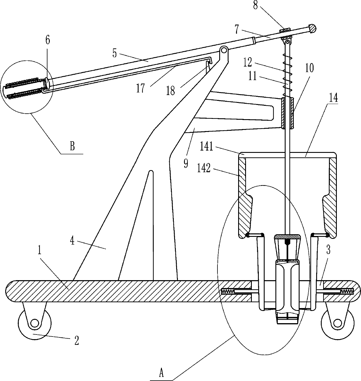
[0016] A boundary post locator for land planning, such as Figure 1-3 As shown, it includes base plate 1, wheel 2, bracket 4, swing rod 5, handle 6, sliding rod 7, sliding sleeve 8, connecting frame 9, guide sleeve 10, guide rod 11, first spring 12 and slotting device 13 , the left and right sides of the bottom of the bottom plate 1 are rotatably connected with wheels 2 for movement, the right part of the bottom plate 1 is provided with an opening 3 for guiding, the bracket 4 is arranged on the left side of the top of the bottom plate 1, and the bracket 4 is welded The way of connection is connected with the bottom plate 1, the swing rod 5 is connected to the upper part of the bracket 4 in a rotational manner, the left end of the swing rod 5 is fixedly connected with the handle 6, the swing rod 5 is connected with the handle 6 by welding, and the right end of the swing rod 5 is fixed Slide bar 7 is arranged, slide bar 7 slide type is provided with the slide sleeve 8 that plays...

Embodiment 2

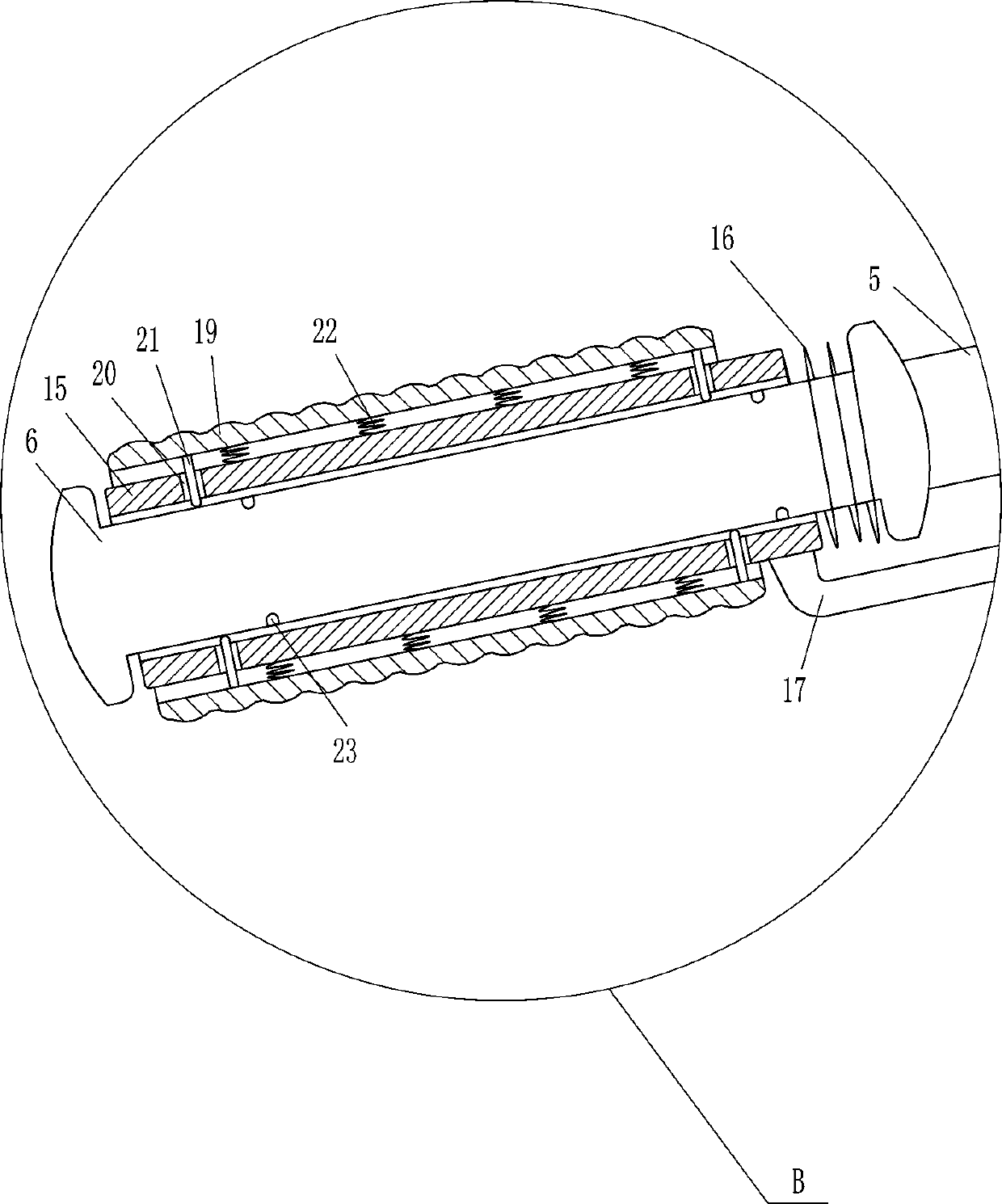
[0018] A boundary post locator for land planning, such as Figure 1-3 As shown, it includes base plate 1, wheel 2, bracket 4, swing rod 5, handle 6, sliding rod 7, sliding sleeve 8, connecting frame 9, guide sleeve 10, guide rod 11, first spring 12 and slotting device 13 , the left and right sides of the bottom of the bottom plate 1 are rotatably connected with wheels 2 for movement, the right part of the bottom plate 1 is provided with an opening 3 for guiding, the bracket 4 is arranged on the left side of the top of the bottom plate 1, and the swing rod 5 rotates The left end of the swing rod 5 is fixedly connected with a handle 6, the right end of the swing rod 5 is fixed with a slide bar 7, and the slide bar 7 is slidably provided with a sliding sleeve 8 which plays a guiding role, and the right side of the support 4 The upper part of the surface is equipped with a connecting frame 9, the right side of the connecting frame 9 is provided with a guide sleeve 10, and a guide ...

Embodiment 3

[0021] A boundary post locator for land planning, such as Figure 1-3 As shown, it includes base plate 1, wheel 2, bracket 4, swing rod 5, handle 6, sliding rod 7, sliding sleeve 8, connecting frame 9, guide sleeve 10, guide rod 11, first spring 12 and slotting device 13 , the left and right sides of the bottom of the bottom plate 1 are rotatably connected with wheels 2 for movement, the right part of the bottom plate 1 is provided with an opening 3 for guiding, the bracket 4 is arranged on the left side of the top of the bottom plate 1, and the swing rod 5 rotates The left end of the swing rod 5 is fixedly connected with a handle 6, the right end of the swing rod 5 is fixed with a slide bar 7, and the slide bar 7 is slidably provided with a sliding sleeve 8 which plays a guiding role, and the right side of the support 4 The upper part of the surface is equipped with a connecting frame 9, the right side of the connecting frame 9 is provided with a guide sleeve 10, and a guide ...


PUM


Abstract

The invention relates to a boundary pile locator, in particular to a boundary pile locator for land planning. According to the technical purpose, the boundary pile locator for land planning is provided, positioning marks are special, and manpower can be reduced. According to the technology implementing scheme, the boundary pile locator for land planning comprises a bottom plate, wheels and the like. The left side and the right side of the bottom of the bottom plate are rotationally connected with the wheels achieving the moving function, and a hole achieving the guiding function is formed in the right portion of the bottom late. A slotting device can be used for conducting groove excavation in the ground, and accordingly, a user can rapidly position a boundary pile; through the special positioning marks, the user can conveniently conduct recognition, accordingly, the user does not need to hold a hoe or shovel for boundary pile positioning and mark making, and manpower can be reduced; and through a soil scraping device, soil in a hollow barrel can be treated, and accordingly the user can conveniently use the boundary pile locator to position the boundary pile next time.

Description

technical field [0001] The invention relates to a boundary post locator, in particular to a boundary post locator for land planning. Background technique [0002] In order to facilitate the installation of boundary posts, people need to locate them, mark the installation place, and then install them. At present, when installing boundary posts, people usually use hoes or shovels to locate and mark the boundary posts. However, shoveling or digging out a positioning and marking at the installation place is easy to be misunderstood, because the marks made by shovels and hoes are very common, so misunderstandings are easy to occur, and it takes a long time to mark with shovels and hoes at the same time , which requires a lot of manpower. Contents of the invention [0003] In order to overcome the shortcomings that the traces made by shovels and hoes are very common, it is easy to be misunderstood, and it takes a long time to consume a lot of manpower. The technical problem of ...

Claims


Application Information

Patent Timeline
Patent Type & Authority Applications(China)
IPC IPC(8): E02F5/20
CPCE02F5/20
Inventor 颜昌文李定华邹瑜江玮
Owner JIANGXI COLLEGE OF APPLIED TECH
Why Eureka
Try Eureka