Stepless transmission
A continuously variable transmission, bucket wheel technology, applied in gear transmission, fluid transmission, transmission elements, etc., can solve the problems of insufficient output torque, the inability of the continuously variable transmission to increase functions and meet more working conditions, etc.
- Summary
- Abstract
- Description
- Claims
- Application Information
AI Technical Summary
Problems solved by technology
Method used
Image
Examples
Embodiment 1
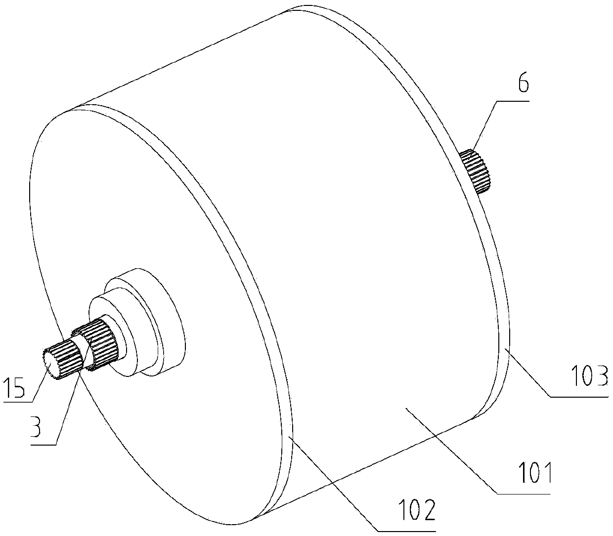
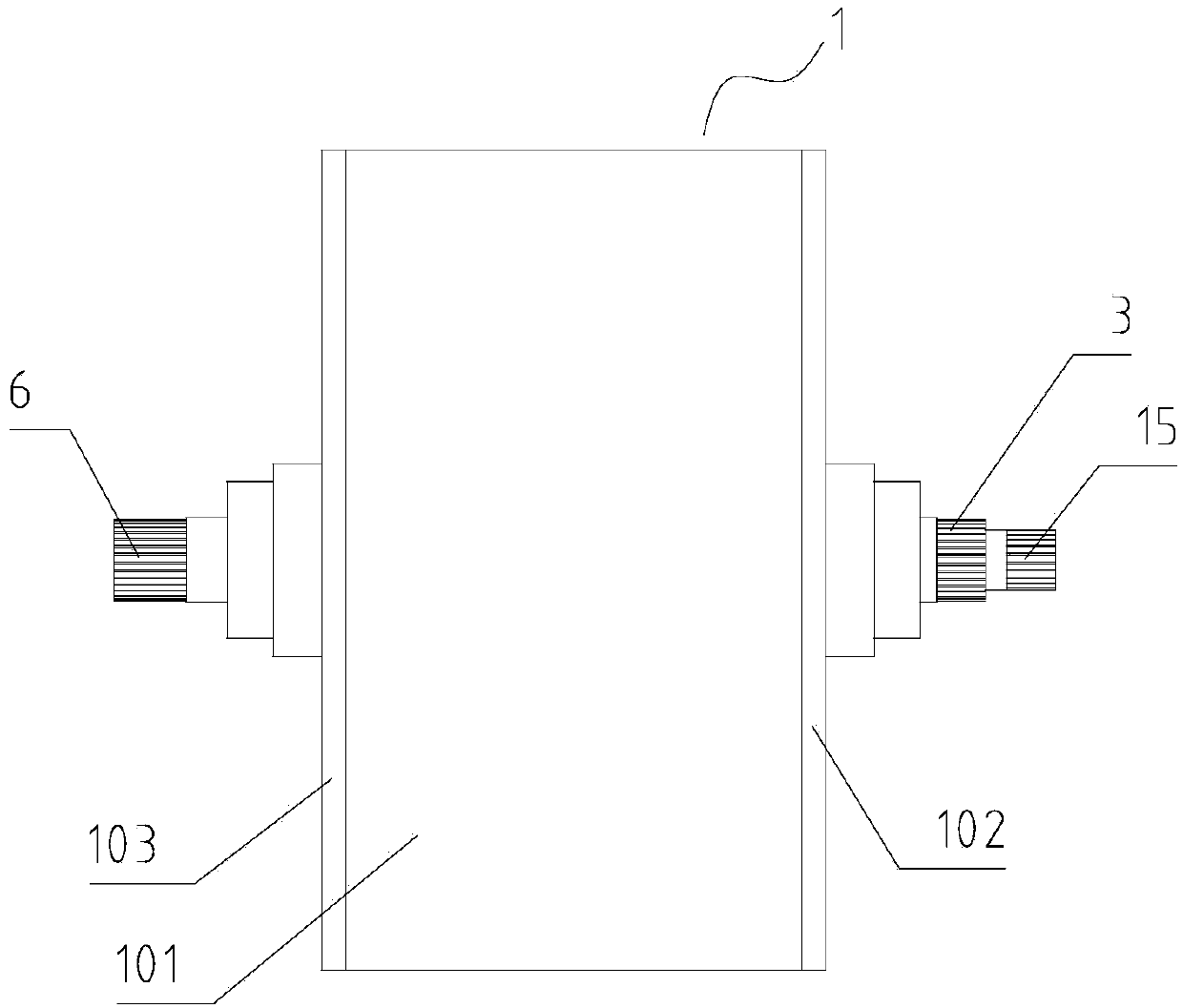
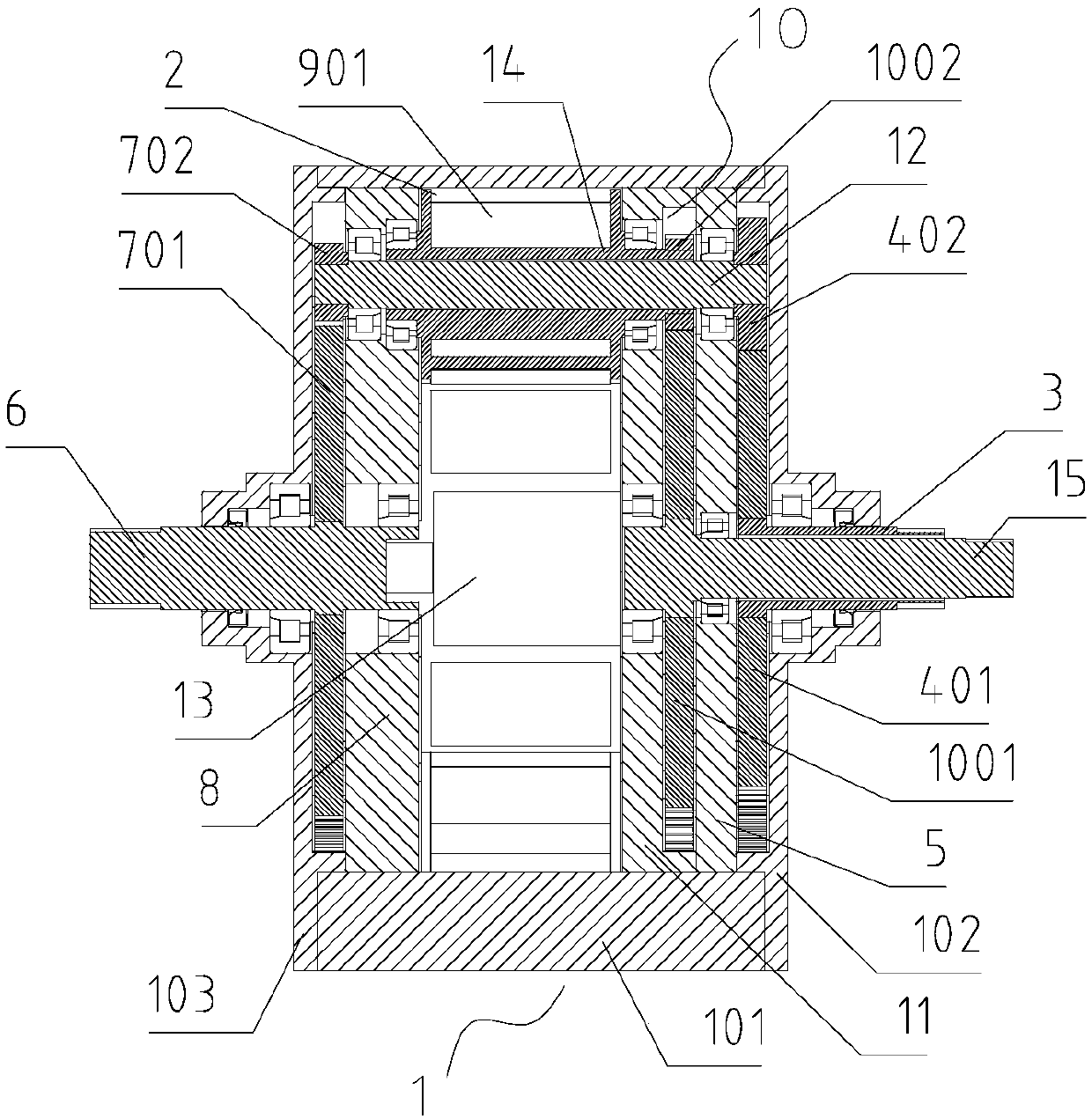
[0031] Such as Figure 1-6 As shown, it is an embodiment of a continuously variable transmission of the present invention, an outer casing 1 is provided, an intermediate casing 101 is arranged in the middle of the outer casing 1, and a first end cover 102 and a second end cover 102 are respectively arranged on both sides of the intermediate casing 101. The cover 103, the interior of the intermediate housing 101 is a cavity structure, and the cavity inside the intermediate housing 101 forms an inner cavity 2 with the inner side of the first end cover 102 and the second end cover 103;
[0032] The middle of the first end cover 102 is provided with a first shaft 3 , the interior of the first shaft 3 is a hollow structure, the first shaft 3 is rotatably connected with the first end cover 102 , and the first sun gear 401 is fixed on the first shaft 3 . The first sun gear 401 is located inside the first end cover 102, the first support frame 5 is adjacent to the first sun gear 401, ...
Embodiment 2
[0044] Figure 7-12 It is the embodiment 2 of a continuously variable transmission of the present invention. It is provided with an outer casing 1, an intermediate casing 101 is arranged in the middle of the outer casing 1, and a first end cover 102 and a second end cover 103 are respectively arranged on both sides of the intermediate casing 101. , the interior of the middle housing 101 is a cavity structure, and the cavity inside the middle housing 101 forms an inner cavity 2 with the inside of the first end cover 102 and the second end cover 103; the first end cover 102 is provided with a first Shaft 3, the inside of the first shaft 3 is a hollow structure, the first shaft 3 is rotatably connected to the first end cover 102, the first shaft 3 is fixed with a first ring gear 401A, and the first ring gear 401A is located on the first end cover 102 On the inner side, the first support frame 5 is adjacent to the first ring gear 401A, and the first planetary gear 402 is arranged ...
Embodiment 3
[0048] refer to image 3 , Figure 6 , Figure 9 and Figure 12 , can form embodiment 3 of the present invention, a kind of continuously variable transmission, is provided with outer casing 1, and middle casing 101 is arranged in the middle of outer casing 1, and the two sides of intermediate casing 101 are respectively provided with first end cover 102 and second The end cover 103, the inside of the middle housing 101 is a cavity structure, the cavity inside the middle housing 101 and the inner side of the first end cover 102 and the second end cover 103 form an inner cavity 2; the first end cover 102 runs through the middle There is a first shaft 3, the interior of the first shaft 3 is a hollow structure, the first shaft 3 is rotatably connected with the first end cover 102, and the first sun gear 401 is fixed on the first shaft 3, and the first sun gear 401 is located at the first Inside the end cover 102, the first support frame 5 is adjacent to the first sun gear 401, ...
PUM
 Abstract
Description
Claims
Application Information
 - R&D
- Intellectual Property
- Life Sciences
- Materials
- Tech Scout
- Unparalleled Data Quality
- Higher Quality Content
- 60% Fewer Hallucinations
Browse by: Latest US Patents, China's latest patents, Technical Efficacy Thesaurus, Application Domain, Technology Topic, Popular Technical Reports.
© 2025 PatSnap. All rights reserved.Legal|Privacy policy|Modern Slavery Act Transparency Statement|Sitemap|About US| Contact US: help@patsnap.com


