Spring structure for machine tools

A technology of spring structure and machine tool, which is applied in the direction of spring, spring/shock absorber, shock absorber-spring combination, etc., can solve problems such as unsatisfactory, poor cushioning accuracy, etc., to achieve improved practicability, simple structure, and improved cushioning The effect of precision

Active Publication Date: 2021-07-09
杭州岚尔滨智能设备有限公司
View PDF12 Cites 0 Cited by
  • Summary
  • Abstract
  • Description
  • Claims
  • Application Information

AI Technical Summary

Problems solved by technology

[0004] The above-mentioned compression spring achieves the cushioning effect through the two spring bodies, but because the buffer range of the two spring bodies is fixed, the cushioning accuracy is not good, and it cannot meet the needs of high-precision working conditions

Method used


Image

  • Spring structure for machine tools
  • Spring structure for machine tools
  • Spring structure for machine tools

Examples


Embodiment Construction

[0021] The following are specific embodiments of the present invention and in conjunction with the accompanying drawings, the technical solutions of the present invention are further described, but the present invention is not limited to these embodiments.

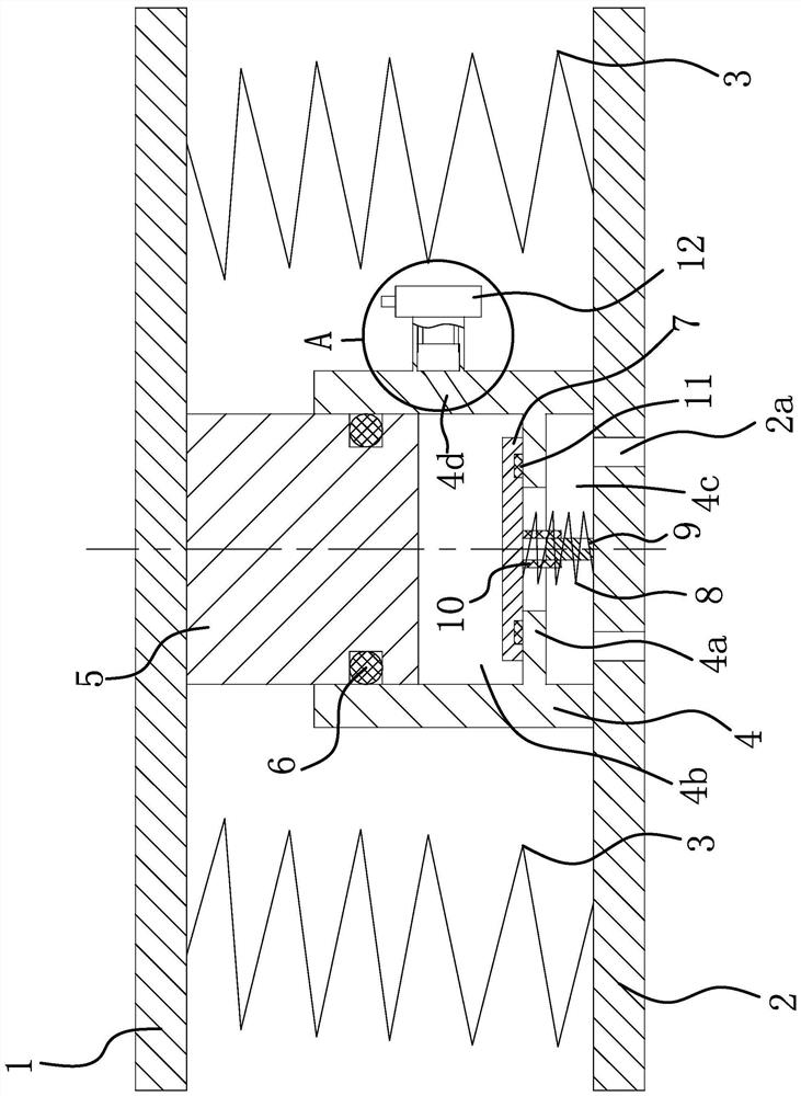
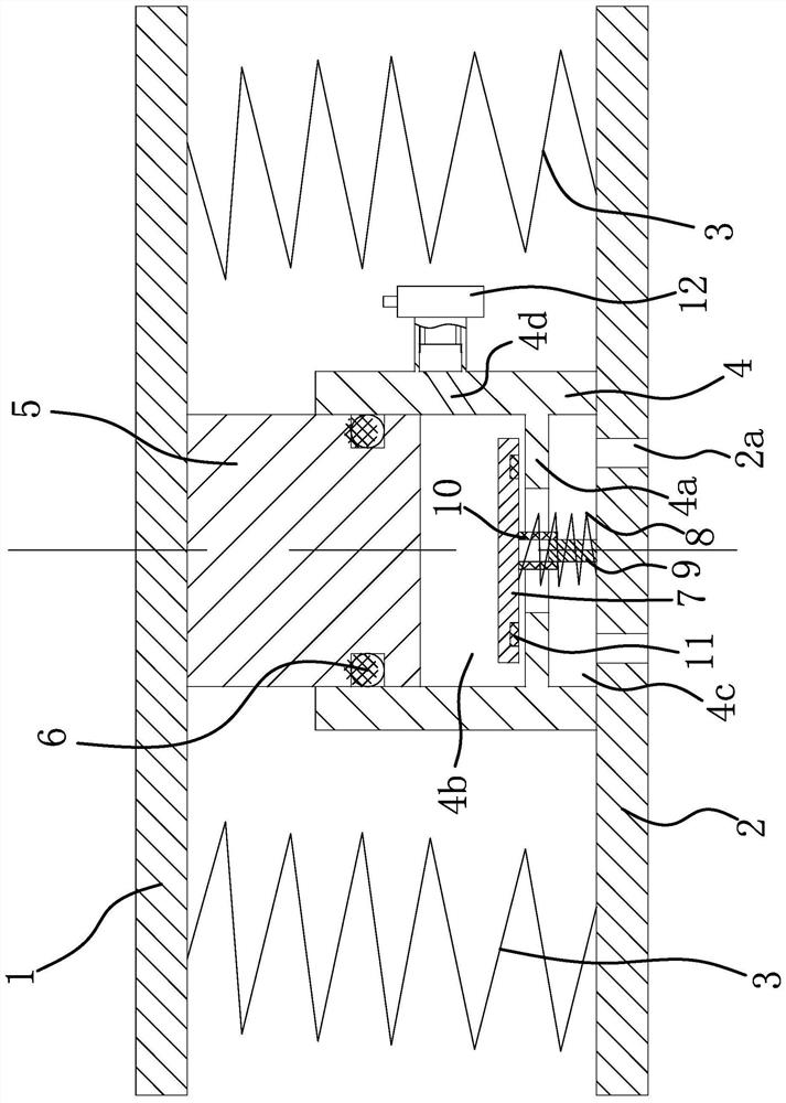
[0022] Such as figure 1 As shown, the spring structure for this machine tool includes an upper plate 1 and a lower plate 2 facing to each other and a compression spring 3 vertically arranged between the upper plate 1 and the lower plate 2. There are two compression springs 3 arranged side by side. In this embodiment, both ends of the compression spring 3 are fixedly connected to the upper plate 1 and the lower plate 2 respectively by welding.

[0023] Specifically, an air cylinder 4 is vertically provided between the two compression springs 3 , and the lower end of the air cylinder 4 is fixedly connected to the lower plate 2 . Preferably, the gas cylinder 4 and the lower plate 2 are fixedly connected by welding. Vertical...


PUM


Abstract

The invention provides a spring structure for a machine tool, which belongs to the technical field of machinery. The spring structure used in this machine tool includes an upper plate, a lower plate, and a compression spring between the upper plate and the lower plate. There are two compression springs, and an air cylinder is arranged between the two compression springs. There is a connecting rod, the upper end of the connecting rod is fixedly connected with the upper plate, and a seal is formed between the side wall of the lower end of the connecting rod and the inner wall of the gas cylinder; an annular shoulder is formed on the inner wall of the lower end of the gas cylinder, and the annular shoulder divides the inner cavity of the gas cylinder into an upper cavity and a lower cavity , the upper cavity is provided with a sealing plate, the outer diameter of the sealing plate is smaller than the inner diameter of the upper cavity, the sealing plate is slidably connected with the gas cylinder, the sealing plate is against the annular shoulder and closes the upper port of the annular shoulder, and the lower cavity is provided so that the sealing plate has The telescopic spring that moves upwards and opens the upper port of the ring-shaped shoulder has an air hole that communicates with the upper cavity through the side wall of the gas cylinder. Vent. The present invention has higher precision.

Description

technical field [0001] The invention belongs to the technical field of machinery and relates to a machine tool accessory, in particular to a spring structure for a machine tool. Background technique [0002] A spring is a mechanical part that uses elasticity to work. Parts made of elastic materials are deformed under the action of external force, and return to their original shape after the external force is removed. [0003] Existing springs such as a compression spring disclosed in the Chinese Patent Library [Application No.: 201620912062.4] include a spring body, the two ends of the spring body are provided with end face fixing panels, the spring body is a pair of cylindrical hollow spiral bodies, and the fixing panels are with fixed The round pancake panel of the buckle of the two helical bodies of the spring body, the buckle is arranged on the outside of the spring body along the direction parallel to the central axis of the spring body. [0004] The above-mentioned co...

Claims


Application Information

Patent Timeline
Patent Type & Authority Patents(China)
IPC IPC(8): F16F13/00F16F1/04F16F9/02F16F9/43
CPCF16F1/04F16F9/0209F16F9/435F16F9/437F16F13/007B23Q11/0032F16F9/0218F16F15/0232F16F15/046F16F15/06B23Q1/01F16F15/027F16F15/04
Inventor 陈武夷
Owner 杭州岚尔滨智能设备有限公司
Why Eureka
Try Eureka