An elevator car floor structure

A technology of elevator car and underframe, which is applied in the field of elevators and can solve problems such as impact and reduced service life of elevators

Active Publication Date: 2021-12-31
上海申菱电梯配件有限公司
View PDF17 Cites 0 Cited by
  • Summary
  • Abstract
  • Description
  • Claims
  • Application Information

AI Technical Summary

Problems solved by technology

[0004] In view of the above-mentioned related technologies, the inventor believes that there is a moment when the user steps into the car bottom of the car, and when the heavy object is placed in the car, it will cause a large impact on the car bottom of the elevator, which will cause a long-term use. Greatly reduce the service life of the elevator

Method used


Image

  • An elevator car floor structure
  • An elevator car floor structure
  • An elevator car floor structure

Examples


Embodiment Construction

[0036] The following is attached Figure 1-6 The application is described in further detail.

[0037] The embodiment of the present application discloses an elevator car bottom structure.

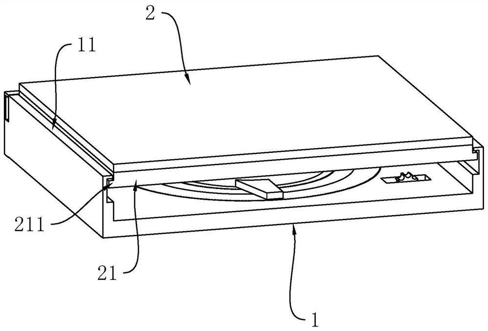
[0038] refer to figure 1, an elevator car floor structure, comprising a horizontally arranged underframe 1, a bottom plate 2 is horizontally arranged on the upper side of the underframe 1, both the underframe 1 and the bottom plate 2 are rectangular, and the size of the bottom plate 2 is smaller than that of the underframe 1, A reinforcing frame 21 is fixedly connected to the outer side of the lower surface of the base plate 2, and the lower ends of the two outer walls of the reinforcing frame 21 are fixedly connected with a horizontal limiting plate 211, and the positions of the corresponding limiting plates 211 on both sides of the chassis 1 tend to be close to each other. direction bending to form a horizontally arranged limiting plate 2 11, the limiting plate 11 is located above the l...


PUM


Abstract

The application relates to an elevator car floor structure, which includes an underframe and a bottom plate. The upper surface of the underframe corresponds to the bottom of the middle part of the bottom plate, and a rotating column is rotatably connected with it. There is a ring sleeve that can be set on the outside of the rotating column. The lower end of the inner peripheral surface of the ring sleeve is rotatably connected with a roller that can roll along the spiral groove; An adjustment disc is arranged horizontally on the side, and one end of the adjustment disc corresponding to each arc-shaped groove is fixedly connected with a fixed plate, and the arc-shaped groove is fixedly connected with a handle that can push the end of the arc-shaped groove away from the fixed plate to move away from the fixed plate under normal conditions. push spring. The application has the effect of realizing the cushioning of the car bottom in the car.

Description

technical field [0001] The present application relates to the field of elevators, in particular to an elevator car bottom structure. Background technique [0002] Elevator refers to the permanent transportation equipment that serves several specific floors in the building, and its car runs on at least two rigid rails that are perpendicular to the horizontal plane or at an inclination angle of less than 15° from the plumb line. Modern elevators are mainly composed of traction machines (winches), guide rails, counterweight devices, safety devices (such as speed limiters, safety gears and buffers, etc.), signal control systems, cars and hall doors. These parts are respectively installed in the hoistway and machine room of the building. Steel wire rope friction transmission is usually used. The wire rope goes around the traction sheave, and the two ends are respectively connected to the car and the counterweight. The motor drives the traction sheave to lift the car up and down....

Claims


Application Information

Patent Timeline
Patent Type & Authority Patents(China)
IPC IPC(8): B66B11/02
CPCB66B11/0226B66B11/0266
Inventor 王杰
Owner 上海申菱电梯配件有限公司
Why Eureka
Try Eureka