Pressure feedback cylinder buffer device

A buffer device and feedback technology, applied in the direction of fluid pressure actuation device, servo motor assembly, mechanical equipment, etc., can solve the problems of poor self-adaptive ability, unable to realize self-adjusting buffer, etc., and achieve reasonable structure layout and strong practicability. , changing the effect of the buffer effect

Inactive Publication Date: 2017-08-25
DALIAN MARITIME UNIVERSITY
View PDF6 Cites 0 Cited by
  • Summary
  • Abstract
  • Description
  • Claims
  • Application Information

AI Technical Summary

Problems solved by technology

[0003] In response to the above problems, the present invention researches and designs a pressure feedback type cylinder buffer device, which is used to solve the problem of the existing overflow type buffer and needle valve type buffer for the change of working conditions such as mass load, speed, and air supply pressure. Poor self-adaptive ability, unable to achieve better self-adjusting buffer

Method used


Image

  • Pressure feedback cylinder buffer device
  • Pressure feedback cylinder buffer device
  • Pressure feedback cylinder buffer device

Examples


Embodiment 1

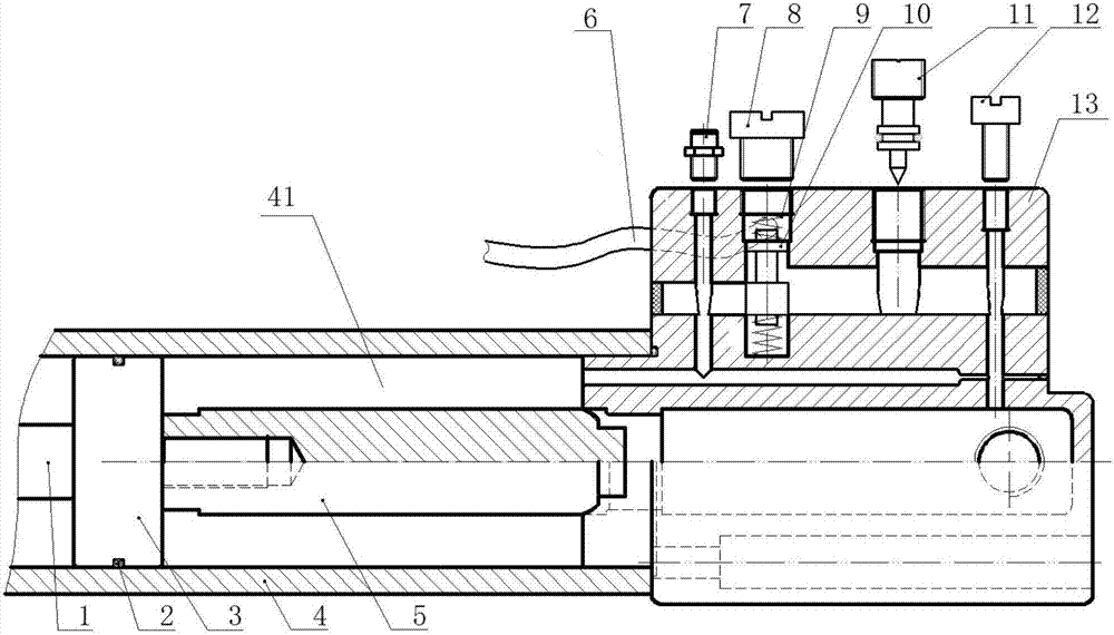
[0063] Embodiment 1, as shown in the figure, a pressure feedback type cylinder buffer device, including a buffer end cover 13 and a cylinder 4 fixedly installed at the front end of the buffer end cover 13, the buffer cavity 41 of the cylinder 4 A piston rod assembly 1 is installed.

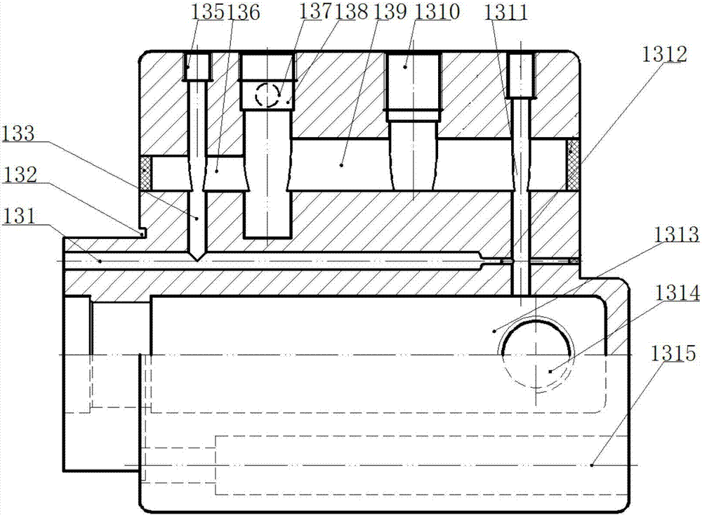
[0064] The end cover body of the buffer end cap 13 is provided with a hexagon socket bolt through hole 1315 for connecting and fixing the buffer end cap 13 and its front end cylinder 4, and four screws pass between the buffer end cap 13 and the cylinder 4 Cooperate and fix, and install in the through hole 1315 of the inner hexagonal bolt. The main body of the buffer end cap 13 is provided with a seal ring installation groove 132 for sealing between the buffer end cap 13 and the cylinder barrel 4, and is installed in the seal ring installation The O-ring in the groove 132 ensures the sealing between the buffer end cover 13 and the cylinder tube 4 .

[0065] The piston rod assembly 1 includes a pis...

Embodiment 2

[0073] Embodiment 2, as shown in the figure, a pressure feedback cylinder buffer device, including a buffer end cap 13 and a cylinder 4 fixedly installed at the front end of the buffer end cap 13, the buffer chamber 41 of the cylinder 4 A piston rod assembly 1 is installed.

[0074]The end cover body of the buffer end cap 13 is provided with a hexagon socket bolt through hole 1315 for connecting and fixing the buffer end cap 13 and its front end cylinder 4, and four screws pass between the buffer end cap 13 and the cylinder 4 Cooperate and fix, and install in the through hole 1315 of the inner hexagonal bolt. The main body of the buffer end cap 13 is provided with a seal ring installation groove 132 for sealing between the buffer end cap 13 and the cylinder barrel 4, and is installed in the seal ring installation The O-ring in the groove 132 ensures the sealing between the buffer end cover 13 and the cylinder tube 4 .

[0075] The piston rod assembly 1 includes a piston 3 and...


PUM


Abstract

The invention discloses a pressure feedback type air cylinder buffering device. The pressure feedback type air cylinder buffering device comprises a buffering end cover and a cylinder barrel fixedly installed at the front end of the buffering end cover, and a piston rod assembly is installed in a buffering cavity of the cylinder barrel; a valve core cavity communicating with a drainage channel in an end cover body is arranged inside the end cover body of the buffering end cover, and a buffering valve core is arranged inside the valve core cavity. When the pressure feedback type air cylinder buffering device carries out buffering, gas in the buffering cavity can flow to two branches, one branch sequentially passes through the buffering cavity and a normally-open drainage port and is finally guided to a plunger cavity, and the other branch sequentially passes through the buffering cavity, an upstream drainage hole, a small-triangle drainage channel, a large-triangle drainage channel and a downstream drainage hole and is finally guided to the plunger cavity. Through cooperation between the buffering valve core and a buffering plunger inside the buffering end cover, good buffering effect is realized.

Description

technical field [0001] The invention relates to a buffer cylinder structure, in particular to a pressure feedback type cylinder buffer device. Background technique [0002] At present, modern pneumatic technology is developing in the direction of high speed, but the problem of cushioning the collision between the piston and the end cover at the end of the stroke has always been an urgent problem to be solved in the high speed of the cylinder. At present, the buffering strategies of high-speed cylinders that are widely used are overflow buffering and needle valve buffering. Adjust cushioning. Contents of the invention [0003] In response to the above problems, the present invention researches and designs a pressure feedback type cylinder buffer device, which is used to solve the problem of the existing overflow type buffer and needle valve type buffer for the change of working conditions such as mass load, speed, and air supply pressure. Poor self-adaptive ability, unabl...

Claims


Application Information

Patent Timeline
Patent Type & Authority Patents(China)
IPC IPC(8): F15B15/22F15B15/14F15B13/02
CPCF15B13/02F15B15/1452F15B15/1457F15B15/22
Inventor 王海涛张天泽熊伟关广丰孙长乐度红望马文琦弓永军张增猛侯交义
Owner DALIAN MARITIME UNIVERSITY
Why Eureka
Try Eureka