A truss-type synchronous deployable antenna

A truss-type antenna technology, applied in the field of spaceborne antenna structure design, can solve problems such as winding, small antenna stiffness, and affecting the performance of antenna reflectors

Inactive Publication Date: 2021-07-30
NORTHWESTERN POLYTECHNICAL UNIV
View PDF5 Cites 0 Cited by
  • Summary
  • Abstract
  • Description
  • Claims
  • Application Information

AI Technical Summary

Problems solved by technology

However, the antenna structure is a single-ring loop truss antenna, its deployment and support rigidity is small, and the deployment process is uncontrollable, and the deployment accuracy and reliability are low, which affects the performance of the antenna reflector
[0005] Invention patent CN 104319453 A proposes a "passively driven double-layer ring truss antenna mechanism". The antenna mechanism is characterized by solving the problem that the existing large-diameter single-ring ring truss antenna has low stiffness and cannot meet the rigidity requirements for use. And the drive structure of the existing ring truss antenna mechanism is complicated, and it is easy to wind up when the cable is deployed, but the precise and synchronous deployment of the antenna mechanism cannot be realized, and the deployment accuracy and reliability are low, so it is difficult to ensure that each unit of the antenna mechanism Can be launched smoothly

Method used


Image

  • A truss-type synchronous deployable antenna
  • A truss-type synchronous deployable antenna
  • A truss-type synchronous deployable antenna

Examples


Embodiment 1

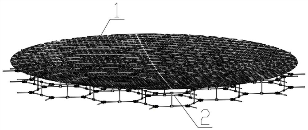
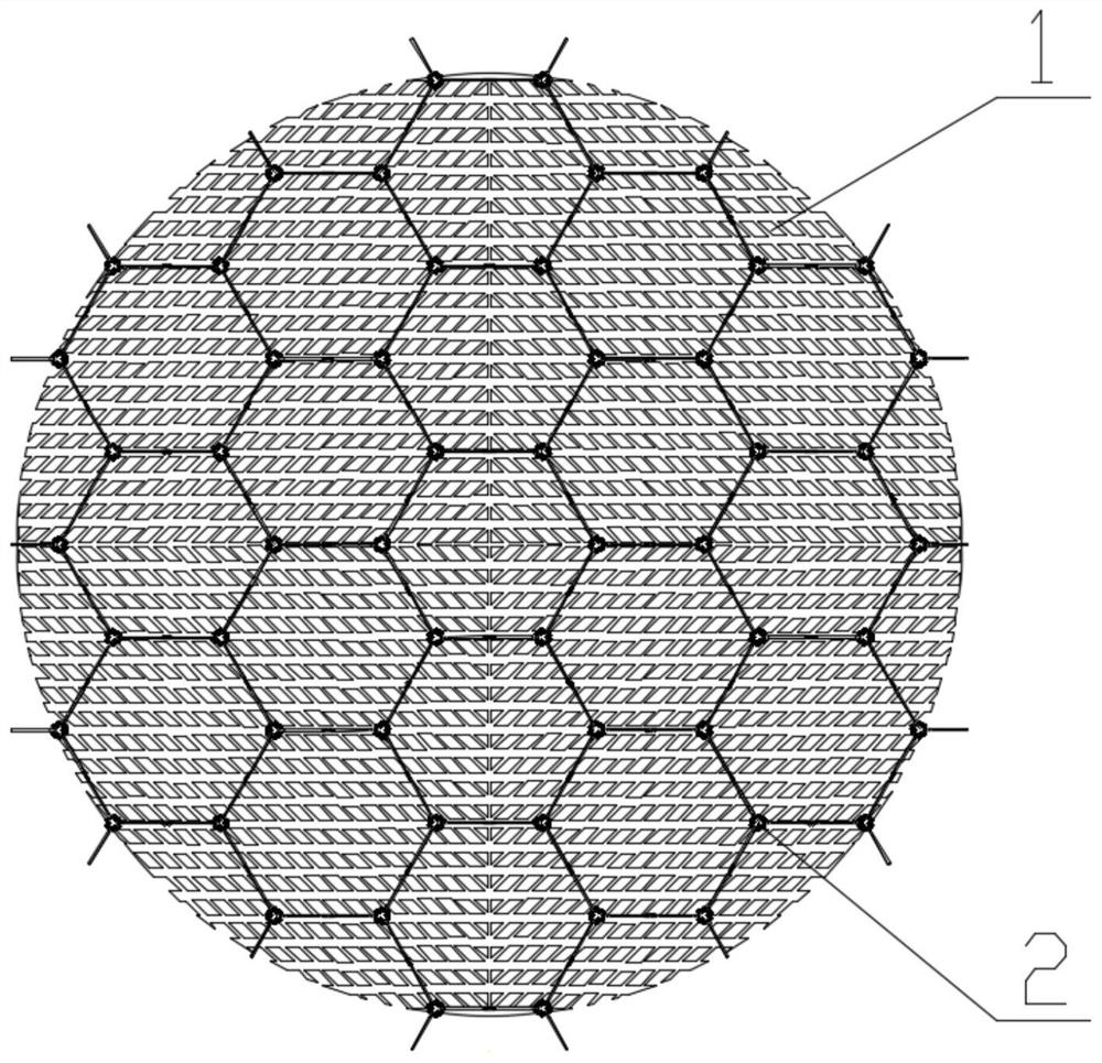
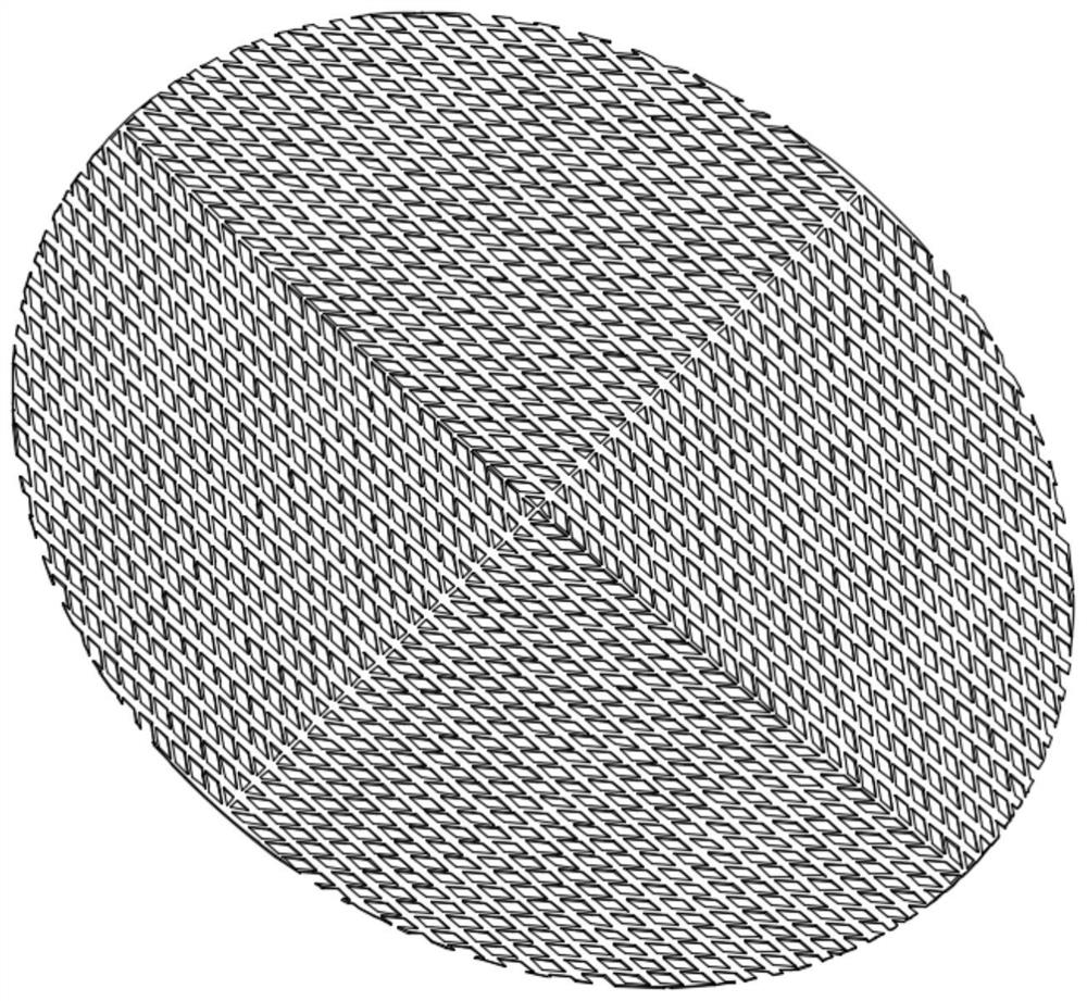
[0059] refer to Figure 1 to Figure 16 In this embodiment, the truss-type synchronously deployable antenna has a deployment diameter of 20 m; it includes the antenna wire net 1, the first synchronously deployable mechanism 2 and the driving assembly for the power device. The drive assembly includes a first drive motor 40 and a second drive motor 41 , and the antenna wire mesh 1 is connected to the first synchronous extendable mechanism 2 .

[0060] In this embodiment, the first synchronous expandable mechanism 2 is a three-dimensional closed-loop synchronous multi-rod symmetrical expandable mechanism composed of a plurality of double-layer combination units 5 of the first synchronous expandable mechanism; the double-layer combination of the first synchronous expandable mechanism The unit 5 includes two basic units 8 of the first synchronous expandable mechanism and 6 first support rods 25, and the double-layer combination unit 5 of the entire first synchronous expandable mecha...

Embodiment 2

[0065] refer to figure 1 , image 3 , Figure 17 ~ Figure 24, In this embodiment, the truss-type synchronous deployable antenna has a deployment diameter of 20 m; it includes the antenna cable net 1, the second synchronous deployable mechanism 3 and the drive assembly for the power device. The drive assembly includes a first drive motor 40 and a second drive motor 41 , and the antenna wire mesh 1 is connected to the second synchronous extendable mechanism 3 .

[0066] In this embodiment, the second synchronous expandable mechanism 3 is a three-dimensional closed-loop synchronous multi-rod symmetrical expandable mechanism composed of a plurality of double-layer combination units 6 of the second synchronous expandable mechanism; the double-layer combination of the second synchronous expandable mechanism The unit 6 includes two basic units 9 of the second synchronous expandable mechanism and three second support rods 26, and the double-layer combination unit 6 of the entire sec...

Embodiment 3

[0069] refer to figure 1 , image 3 , Figure 25 ~ Figure 34 In this embodiment, the truss-type synchronously deployable antenna has a deployment diameter of 20 m; it includes the antenna cable net 1, the third synchronously deployable mechanism 4 and the drive assembly for the power device. The drive assembly includes a first drive motor 40 and a second drive motor 41 , and the antenna wire mesh 1 is connected to the third synchronous extendable mechanism 4 .

[0070] In this embodiment, the third synchronous expandable mechanism 4 is a three-dimensional closed-loop synchronous multi-rod symmetrical expandable mechanism composed of a plurality of double-layer combination units 7 of the third synchronous expandable mechanism; The combination unit 7 includes two basic units of the third synchronous expandable mechanism and four third support rods 27, and the double-layer combination unit 7 of the entire third synchronous expandable mechanism is symmetrical about the middle ci...


PUM


Abstract

The invention discloses a truss-type synchronously deployable antenna, which is composed of an antenna wire net, a synchronously deployable mechanism and a drive assembly; the synchronously deployable mechanism is divided into a first synchronously deployable mechanism, a second synchronously deployable mechanism and a The third synchronously expandable mechanism. The antenna wire net and the driving component respectively form three types of truss-type synchronous deployable antennas with the first synchronous deployable mechanism, the second synchronous deployable mechanism, and the third synchronous deployable mechanism; under the action of the driving component, the antenna wire net The space-synchronous deployment is realized through the synchronous expandable mechanism. After the deployment is completed, under the action of the locking mechanism, the antenna as a whole is stable in a fully deployed state. The truss-type synchronously deployable antenna has the characteristics of large deployment aperture, high storage rate, high spatial synchronization deployment accuracy, and strong support rigidity. The synchronous expandable mechanism can be used in the fields of solar sail panels and retractable roof structure engineering, and the antenna can also be used in space or on the ground as reflectors or concentrators.

Description

technical field [0001] The invention relates to the field of space-borne antenna structure design, in particular to a truss-type synchronous deployable antenna. Background technique [0002] With the development of aerospace science and technology, spacecraft are becoming increasingly large and complex, especially space antennas, space-borne radars, space power stations, etc. have more and more demands for large-scale deployable structures, and related technologies are facing challenges. Unprecedented development opportunities and challenges. With the gradual development of aerospace research programs and the complexity of space systems, the space deployable structure has developed from a simple and single form in the past to a complex, multi-degree-of-freedom, and modular direction; large-scale space deployable structures have become the focus of aerospace science in recent years. Hotspots in the field of technology research. The research on large-scale space-borne deploy...

Claims


Application Information

Patent Timeline
Patent Type & Authority Patents(China)
IPC IPC(8): H01Q15/16H01Q1/08
CPCH01Q15/161
Inventor 王三民卢江昇高举余澍民姚亮司令朱慧玲
Owner NORTHWESTERN POLYTECHNICAL UNIV
Why Eureka
Try Eureka